Page 68
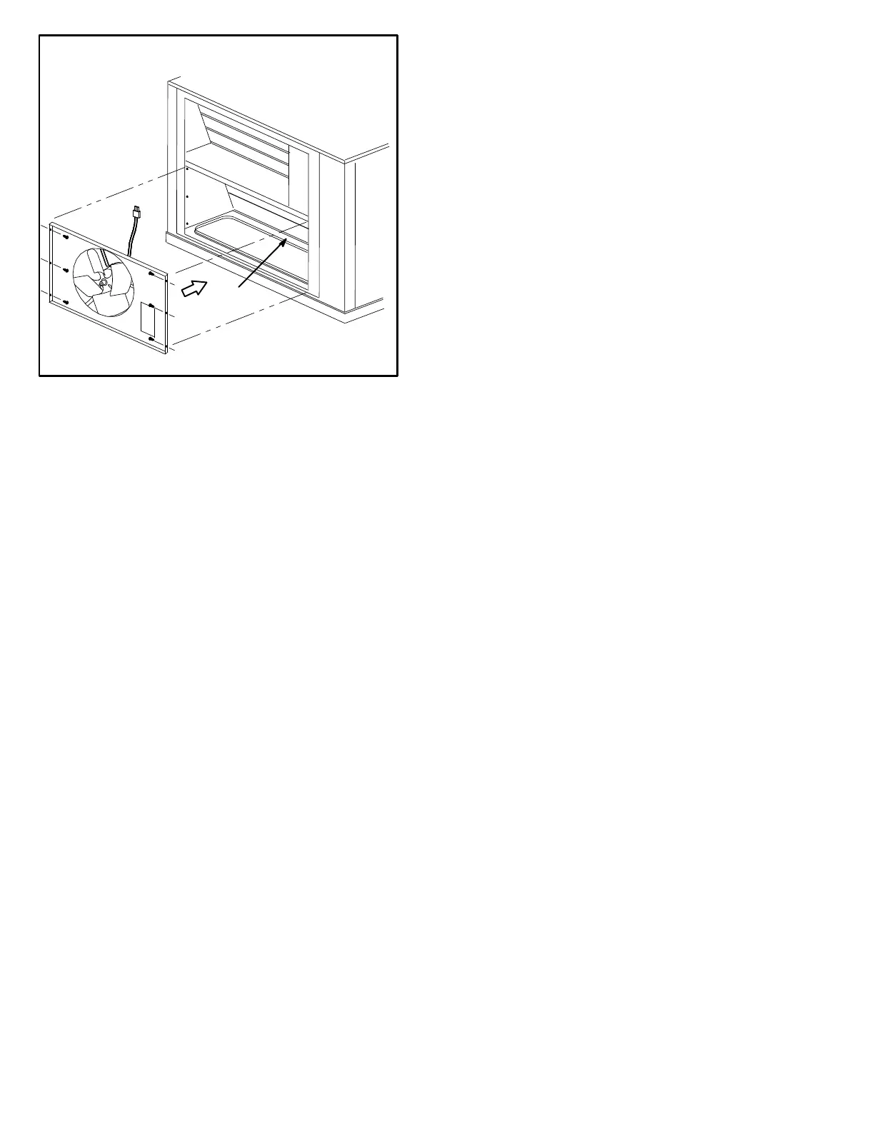
FIGURE 30
P18
POWER EXHAUST FAN
J18 JACK ON
UNDERSIDE OF
DIVISION PANEL
CONNECT P18 TO J18
BEFORE SECURING
EXHAUST FAN IN
PLACE
H-Optional Cold Weather Kit
Electric heater is available to automatically control the
minimum temperature in the gas burner compartment.
Heater is C.S.A. certified to allow cold weather opera
tion of unit down to ‐60° F (‐50° C ).
The kit includes the following parts:
1- The strip heater (HR6) is located as close as possible to the
gas valve. The strip heater is rated at 500 Watts
2- A thermostat mounting box is installed on the wall of
the compressor compartment. Included in the box
are the following thermostat switches:
a - Thermostat switch (S59) is an auto‐reset SPST N.C.
switch which opens on a temperature drop. The
switch is wired in series with 24v power and the com
bustion air blower switch. When the temperature
drops below ‐30° F (-35° C) the switch opens and the
gas heat section is de‐energized. The switch automati
cally resets when the heating compartment tempera
ture reaches -10° F (-12° C).
b - Thermostat switch (S60) is an auto‐reset SPST
N.C. switch which opens on a temperature rise.
The switch is wired in series with HR6. When the
temperature rises above 20° F (‐7° C) the switch
opens and the electric heater is de‐energized. The
switch automatically resets when the heating com
partment temperature reaches ‐10° F (23.3° C).
c -Thermostat switch (S61) is an auto‐reset SPST
N.O. switch which closes on a temperature drop.
The switch is wired in series with HR6. When tem
perature drops below 20° F (‐7° C) the switch clos
es and electric heater is energized. The switch au
tomatically opens when heating compartment
temperature reaches 70° F (21° C).
I-Control Systems
Three different types of control systems may be used with
the KGB series units. All thermostat wiring is connected to
TB1 located in the control box. Each thermostat has addi
tional control options available. See thermostat installation
instructions for more detail.
1- Electro‐mechanical thermostat (13F06)
The electro‐mechanical thermostat is a two stage heat /
two stage cool thermostat with dual temperature levers.
A non‐switching or manual system switch subbase
may be used.
2- Electronic thermostat (see price book)
Any two stage heat / two stage cool electronic ther
mostat may be used.
3- Honeywell T7300 thermostat (60L59)
The Honeywell T7300 thermostat is a programmable, in
ternal or optional remote temperature sensing thermo
stat. The T7300 provides occupied and unoccupied
changeover control.
J-Smoke Detectors A17 and A64
Photoelectric smoke detectors are a field installed option.
The smoke detectors can be installed in the supply air duct
(A64), return air section (A17), or in both the supply duct
and return air section.
K-Dirty Filter Switch S27
The dirty filter switch senses static pressure increase indi
cating a dirty filter condition. The switch is N.O. and closes
at 1” W.C. (248.6 Pa) The switch is mounted in the filter sec
tion on the left unit mullion.
L-Indoor Air Quality (CO
2
) Sensor A63
The indoor air quality sensor monitors CO
2
levels and re
ports the levels to the economizer enthalpy control A6. Con
troller A6 adjusts the economizer dampers according to the
CO
2
levels. The sensor is mounted next to the indoor ther
mostat or in the return air duct. Refer to the indoor air quality
sensor installation instructions for proper adjustment.
M-LP / Propane Kit
All units require a natural to LP /propane kit. The kit for sin
gle stage units include one LP spring , seven burner orifices,
and three stickers. Two stage kits include the same but has a
prove switch used to lock out first stage on the combustion air
inducer. For more detail refer to the natural to LP gas
changeover kit installation instructions.
N-Drain Pan Overflow Switch S149
(optional)
The overflow switch is used to interrupt cooling operation
when excessive condensate collects in the drain pan. The
N.O. overflow switch is controlled by K220 and DL46 relays,
located in the unit control panel. When the overflow switch
closes, 24VAC power is interrupted and after a five-second
delay unit compressors are de-energized. Once the conden
sate level drops below the set level, the switch will open. Af
ter a five-minute delay the compressor will be energized.
 Loading...
