Page 62
2- Remove lead from sensing electrode and install a
0-50DC microamp meter in series between the sens
ing electrode and the sensing lead.
3- Reconnect power and adjust thermostat for
heating demand.
4- When flame is established, microamp reading should
be 0.5 to 1.0. Do not bend electrodes.
Drop out signal is .09 or less.
5- Disconnect power to unit before disconnecting meter.
Make sure sensor wire is securely reconnected
before reconnecting power to unit.
NOTE-If the meter scale reads 0, the leads are re
versed. Disconnect power and reconnect leads for
proper polarity.
B-Cooling System Service Checks
KGB units are factory charged and require no further adjust
ment; however, charge should be checked periodically using
the approach method. The approach method compares actual
liquid temperature with the outdoor ambient temperature. See
section IV- CHARGING.
VI-MAINTENANCE
The unit should be inspected once a year by a qualified ser
vice technician.
Electric shock hazard. Can cause injury
or death. Before attempting to perform
any service or maintenance, turn the
electrical power to unit OFF at
disconnect switch(es). Unit may have
multiple power supplies.
WARNING
!
CAUTION
Label all wires prior to disconnection when servicing
controls. Wiring errors can cause improper and dan
gerous operation. Verify proper operation after ser
vicing.
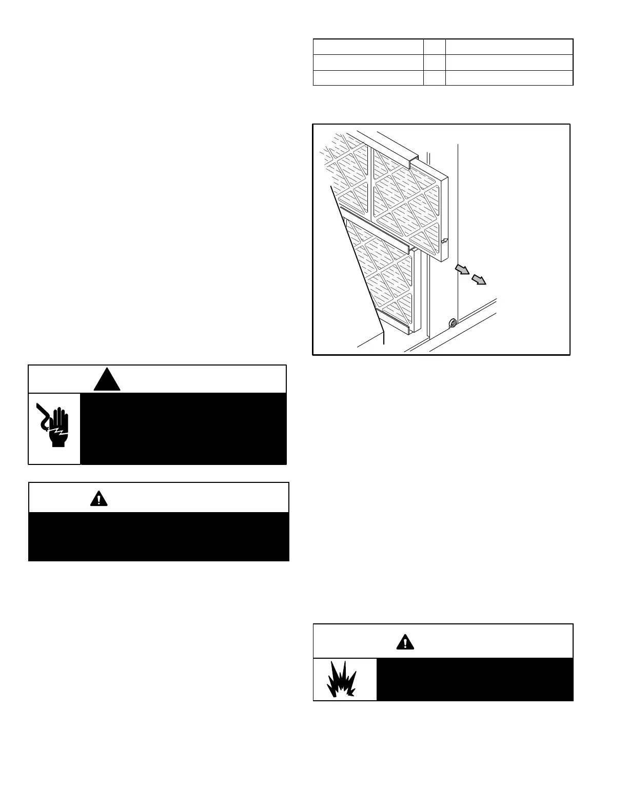
A-Filters
Units are equipped with temporary filters which must be
replaced prior to building occupation. See table 25 for
correct filter size. Refer to local codes or appropriate ju
risdiction for approved filters. Approved filters should be
checked monthly and replaced when necessary. Take note
of air flow direction marking on filter frame when reinstalling
filters
TABLE 25
Unit Qty Filter Size - inches (mm)
024, 030, 036, 048 4 16 X 20 X 2 (406 X 508 X 51)
072, 060, 090 4 20 X 20 X 2 (508 X 508 X 51)
NOTE-Filters must be U.L.C. certified or equivalent for use
in Canada.
FIGURE 23
REMOVE FILTERS
PULL TO
REMOVE
FILTERS
B-Lubrication
All motors are lubricated at the factory. No further lubrica
tion is required.
C-Burners
Periodically examine burner flames for proper appearance
during the heating season. Before each heating season ex
amine the burners for any deposits or blockage which may
have occurred.
Clean burners as follows:
1- Turn off both electrical power and gas supply to unit.
2- Remove burner compartment access panel.
3- Remove top burner box panel.
4- Remove two screws securing burners to burner sup
port and lift the burners from the orifices. See figure 17.
Clean as necessary.
WARNING
Danger of explosion. Can cause injury or
death. Do not overtighten main burner
mounting screws. Snug tighten only.

 Loading...