Page 65
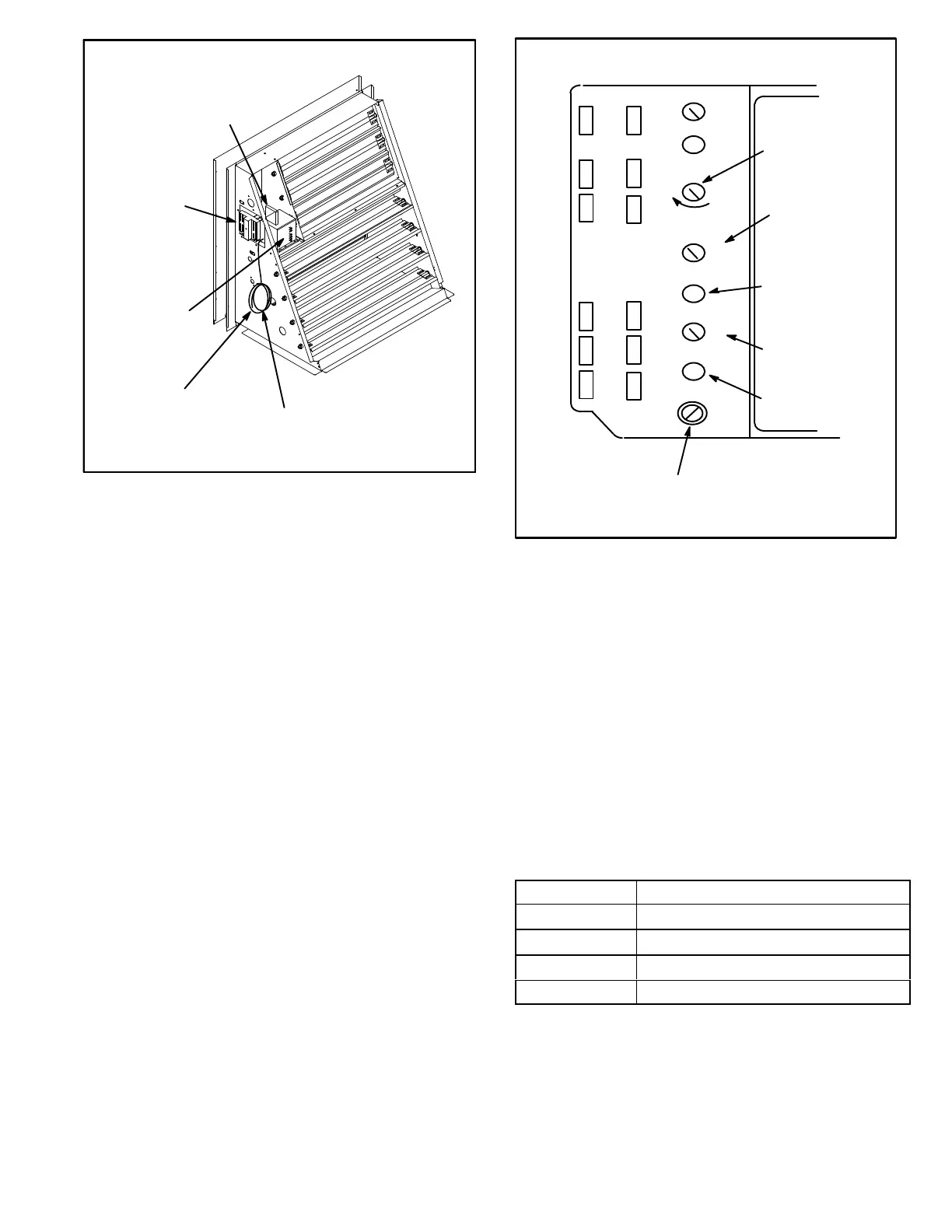
FIGURE 27
ECONOMIZER CONTROLS
A6
ENTHALPY
CONTROL
B7
DAMPER
MOTOR
A7
ENTHALPY
SENSOR (OTHER
SIDE OF PANEL)
POWER EXHAUST WIRES
ONLY CONNECTED WHEN
UNIT IS EQUIPPED WITH
POWER EXHAUST
MIXED AIR SENSOR
(R1) AND WIRING IN
THIS BUNDLE
Optional Sensors
An optional differential sensor (A62) may be used with the
A7 outdoor sensor to compare outdoor air enthalpy to re
turn air enthalpy. When the outdoor air enthalpy is below
the return air enthalpy, outdoor air is used for free cooling.
Mixed air sensor (R1) may be used to modulate dampers to
55
°F (13°C) discharge air.
An optional IAQ sensor (A63) may be used to lower operat
ing costs by controlling outdoor air based on CO
2
level or
room occupancy (also called demand control ventilation or
DCV). Damper minimum position can be set lower than tra
ditional minimum air requirements; dampers open to tradi
tional ventilation requirements when CO
2
level reaches
DCV (IAQ) setpoint.
Refer to instructions provided with sensors for installation.
A6 Enthalpy Control LEDs
A steady green Free Cool LED indicates that outdoor air is
suitable for free cooling.
When an optional IAQ sensor is installed, a steady green
DCV LED indicates that the IAQ reading is higher than set
point requiring more fresh air. See figure 28.
FIGURE 28
A6 ENTHALPY CONTROLLER
A
B
C
D
Open
Min
Pos
FREE COOLING SETPOINT;
A=Completely counterclockwise
D=Completely clockwise
OUTDOOR AIR
SUITABLE LED
Free
Cool
DCV
EXH
EXH
Set
2V 10V
DCV
Max
2V 10V
DCV
Set
2V 10V
IAQ SETPOINT
IAQ READING IS
ABOVE SETPOINT
DAMPER MINI
MUM POSITION
IAQ MAXIMUM
POSITION
(set higher than
minimum position)
Free Cooling Setpoint
Outdoor air is considered suitable when temperature and
humidity are less than the free cooling setpoints shown in
table 26. Setting A is recommended. See figure 28. At set
ting A, free cooling will be energized when outdoor air is ap
proximately 73°F (23°C) and 50% relative humidity. If in
door air is too warm or humid, lower the setpoint to B. At
setting B, free cooling will be energized at 70°F (21°C) and
50% relative humidity.
When an optional A62 differential sensor is installed, turn
A6 enthalpy control free cooling setpoint potentiometer
completely clockwise to position “D”.
TABLE 26
ENTHALPY CONTROL SETPOINTS
Control Setting Free Cooling Setpoint At 50% RH
A
73° F (23° C)
B
70° F (21° C)
C
67° F (19° C)
D
63° F (17° C)
Damper Minimum Position
NOTE - A jumper is factory-installed between TB1 R and
OC terminals to maintain occupied status (allowing mini
mum fresh air). When using an electronic thermostat or
energy management system with an occupied/unoccu
pied feature, remove jumper.

 Loading...