Page 73
GAS HEAT FOR KGB024/090 UNITS
2
7
8
5
4
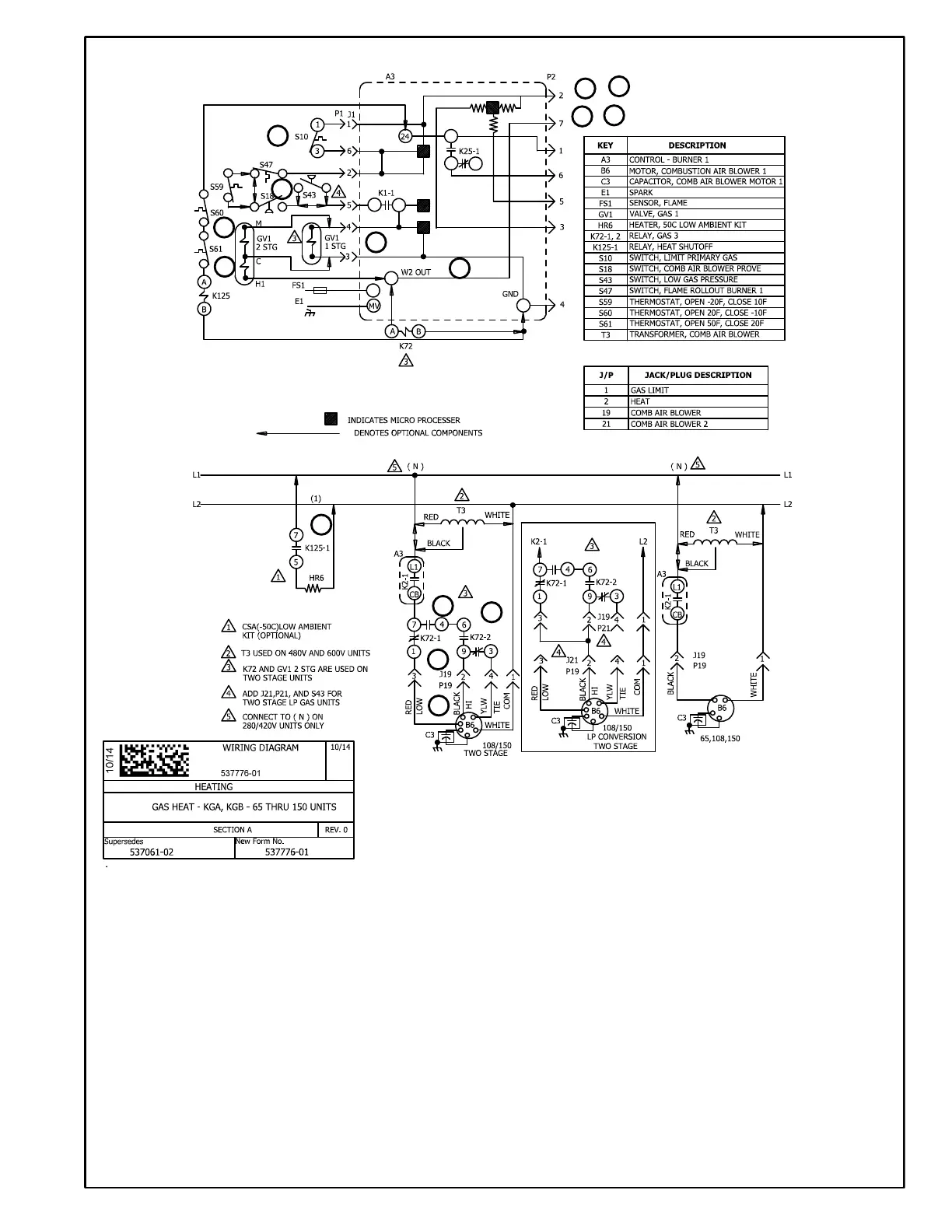
First Stage Heat:
1. The thermostat initiates W1 heating demand.
2. 24VAC is routed from TB1 to ignition control A3. A3 proves N.C. pri
mary limit S10 and N.C. rollout switch S47.
3. Combustion air inducer blower B6 is energized.
4. After the combustion air inducer B6 has reached full speed, the
combustion air proving switch S18 contacts close.
5. After a 30 second delay A3 energizes the ignitor and gas valve GV1
on first stage.
Second Stage Heat:
6. With first stage heat operating, an additional heating demand from
the thermostat initiates W2.
7. A second stage heating demand is received by ignition control A3.
8. A3 energizes gas valve GV1 on second stage.
9. Relay K72-1 terminals 1 and 7 open, 7 and 4 close. K72-2 terminals
6 and 9 close and 9 and 3 open, energizing combustion air inducer
B6 on high speed.
End of Second Stage Heat:
10. Heating demand is satisfied. Terminal W2 (second
stage) is de-energized.
11. Second stage heat is de-energized on GV1 by ignition
control A3.
12. K72 terminals 4 and 7 open and 1 and 7 close. K72
terminals 6 and 9 open, 9 and 3 close. Combustion air
inducer B6 is now on low speed.
End of First Stage Heat:
13. Heating demand is satisfied. Terminal W1 (first stage)
is de-energized.
14. Ignition A3 is de-energized in turn de-energizing gas
valve GV1 and combustion air inducer B6.
Optional Low Ambient Kit:
(C.S.A. -50° C Low Ambient Kit)
15. Line voltage is routed through the N.C. low ambient kit
thermostats S60 and S61,to energize low ambient kit
heater HR6.
1
3
6
9
10
11
12
13
14
15
 Loading...
