15. Service Relay
Page 60
506457−01 05/10
15. Service Relay
15.1. Service Relay Operation
The M2 Service Relay output (A55_P298−8) default operation indicates that service is required. Table 40 indicates these
critical alarms with an asterisk.
If the default operation is not required, the Service Relay output may be used as a control output. Use ECTO 7.22 to choose
the input which will trigger the Service Relay output. The formula X + (32
x
Y) + (16
x
Z) is used to select the option. See table
39.
If ECTO 7.22 input sources 7−9 are used, the setpoint and deadband must be set with ECTO 7.23 and 7.24.
Table 39. Service Relay Options
Control Parameter Control Value
No. Name Min Default Max.
Units Description
7.22
Service_
Output_
Control_Mode
0 0 127 Option
A55 Service Output Control Mode = X + 32*Y + 16*Z
Input source = X:
0− None. Standard Service Output based on alarms.
1− Compressor 1 duty cycle. (Compressor crankcase heater function.)
On when OAT < = ECTO 7.23 and >= ECTO 7.24 seconds have passed
with compressor 1 off. Off when OAT > ECTO 7.23 + 3 deg F (fixed dead-
band) or < ECTO 7.24 seconds have passed with compressor 1 off
2− On when occupied.
3− On when blower on,
4− On when heating demand.
5− On when cooling demand.
6− On when heating or cooling demand.
7− System RH (A55_P298_5 RH)
8− System IAQ. (A55_P298_3 IAQ)
9− System OAT (A55_P267_1/2 OAT)
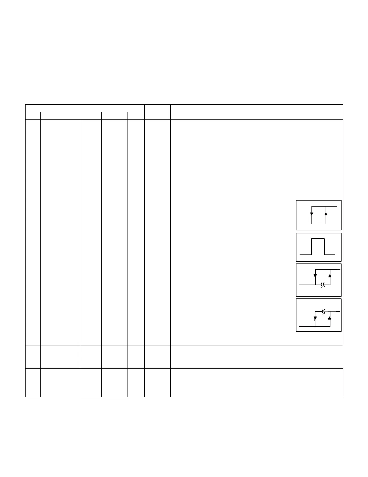
Algorithm Y for input sources 7−9:
0− Hysteresis loop
On when input >= ECTO 7.23
Off when input < ECTO 7.23−ECTO 7.24
1− Window
On when input is in range;
>= ECTO 7.23 and <= ECTO 7.23 + ECTO 7.24
(Fixed 3−count hysteresis loop on rising and
falling edges of window.)
2− Delayed−on.
On when input is >= ECTO 7.23
for >= ECTO 7.24 seconds.
Off when input is < ECTO 7.23−3.
(Fixed 3−count hysteresis loop on edge.)
3− Delayed−off.
On when input is >= ECTO 7.23.
Off when input is < ECTO7.23 − 3
for >= ECTO 7.24 seconds.
(Fixed 3−count hysteresis loop on edge.)
Inversion Z:
0− Output not inverted.
1− Output inverted.
Graphs indicate output not in-
verted. See figure 33.
OFF
ON
Delay
7.24
7.237.23−7.24
OFF
ON
OFF
7.23 7.23+7.24
7.23
OFF
Delay
7.24
ON
ON
OFF
7.23
7.23
Service_
Output_ SP
0
0
0
132
127
996
100
51
255
2000
100
−31
Counts
I:ppm
P: %
Y:DegF
A55 service relay output setpoint.
7.24
Service_
Output_ DB
2
16
2
1
64
13
102
13
8
416
255
2000
100
162
8160
Counts
I:ppm
P: %
O:DegF
D:Sec.
A55 service relay output deadband or delay.