Note: The following procedure is based on the scenario that you are removing the front I/O assembly for
server models with eight 3.5-inch drive bays. The removal procedure is similar for the front I/O assembly for
server models with eight or sixteen 2.5-inch drive bays.
For server models with twelve 3.5-inch drive bays or twenty-four 2.5-inch drive bays, the front I/O assembly
is assembled with the right rack latch. See “Remove the rack latches” on page 95 for the removal
procedures.
Before removing the front I/O assembly:
1. Remove the top cover. See “Remove the top cover” on page 103.
2. If the security bezel is installed, remove it. See “Remove the security bezel” on page 92.
3. Disconnect the cables of the front I/O assembly from the system board. See “Front I/O assembly” on
page 29.
To remove the front I/O assembly, complete the following steps:
Watch the procedure. A video of the removal process is available:
• Youtube:
https://www.youtube.com/playlist?list=PLYV5R7hVcs-A25P7vBoGa_wn7D7XTgDS_
• Youku: http://list.youku.com/albumlist/show/id_50483444
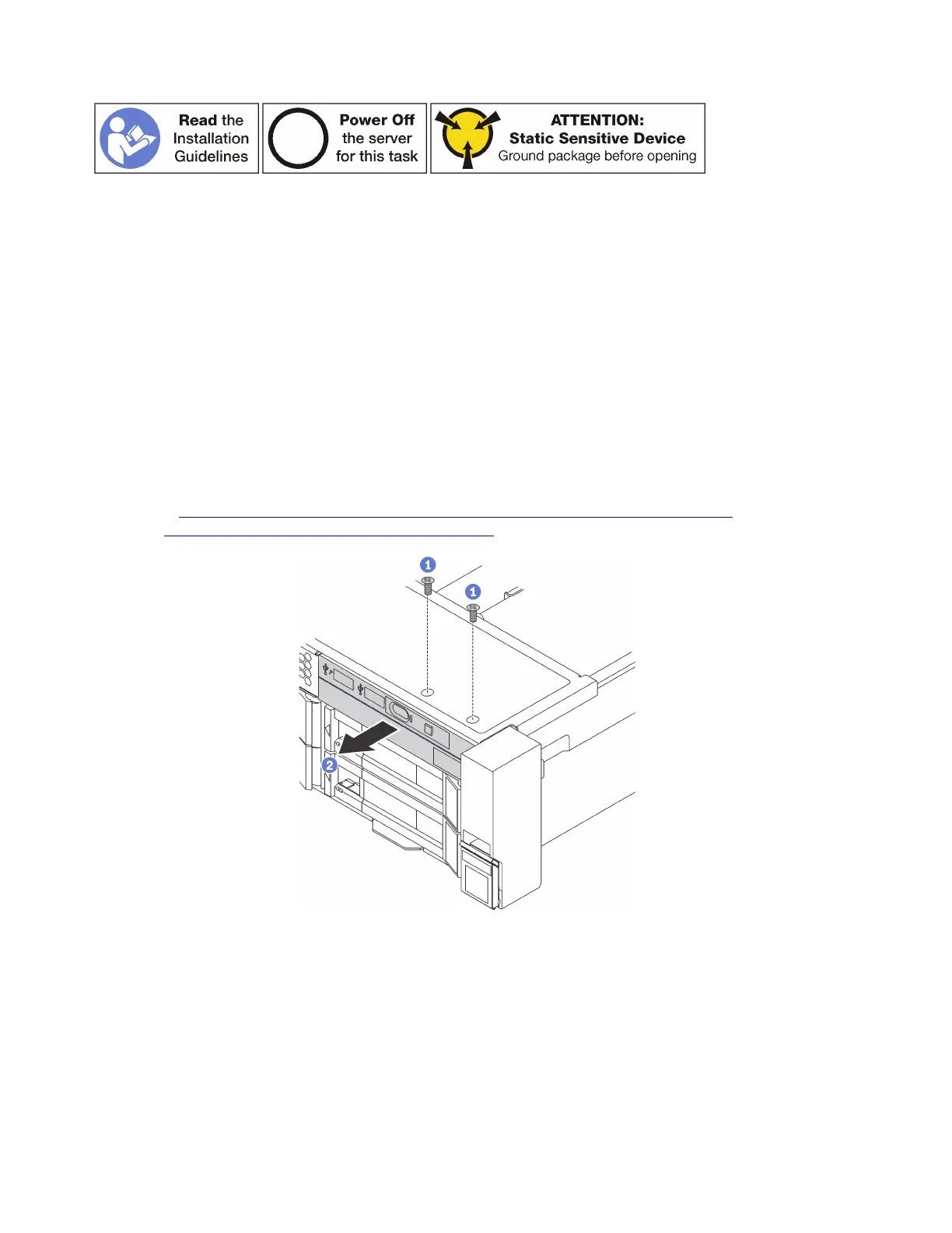
Figure 87. Front I/O assembly removal
Step 1. Remove the screws that secure the front I/O assembly.
Step 2. Slide the front I/O assembly out of the assembly bay.
If you are instructed to return the old front I/O assembly, follow all packaging instructions and use any
packaging materials that are provided.
118
ThinkSystem SR650 Maintenance Manual