Rear view LEDs
The illustration in this section shows the LEDs on the rear of the server.
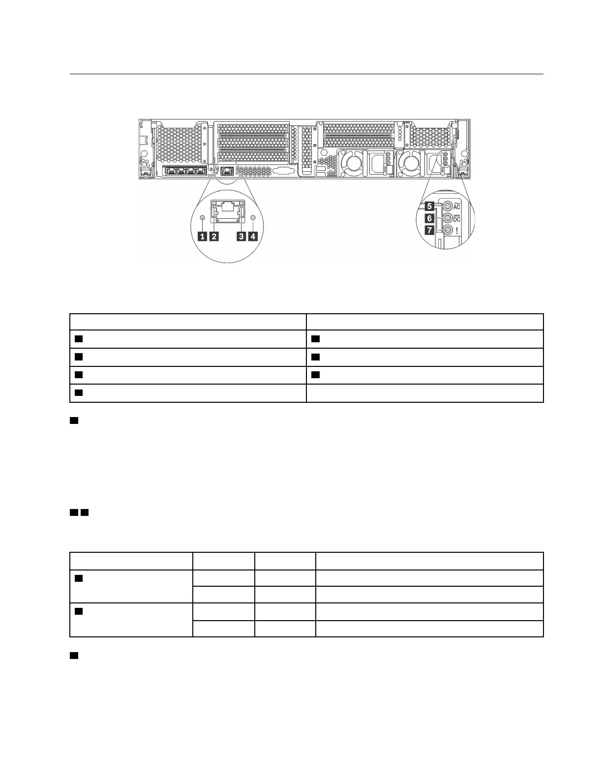
Figure 14. Rear view LEDs of the server
Table 5. LEDs on the rear of the server
Callout Callout
1 System ID LED
2 Ethernet link LED
3 Ethernet activity LED
4 System error LED
5 Power input LED 6 Power output LED
7 Power supply error LED
1 System ID LED
The blue system ID LED helps you to visually locate the server. A system ID LED is also located on the front
of the server. Each time you press the system ID button, the state of both the system ID LEDs changes. The
LEDs can be changed to on, blinking, or off. You can also use the Lenovo XClarity Controller or a remote
management program to change the state of the system ID LEDs to assist in visually locating the server
among other servers.
2 3 Ethernet status LEDs
The XClarity Controller network connector has two status LEDs.
Ethernet status LED Color Status Description
2 Ethernet link LED
Green On
Network link is established.
None
Off
Network link is disconnected.
3 Ethernet activity LED
Green
Blinking Network link is connected and active.
None
Off The server is disconnected from a LAN.
4 System error LED
The system error LED provides basic diagnostic functions for your server. If the system error LED is lit, one or
more LEDs elsewhere in the server might also be lit to direct you to the source of the error. For more
information, see “Front I/O assembly” on page 15.
Chapter 2. Server components 21