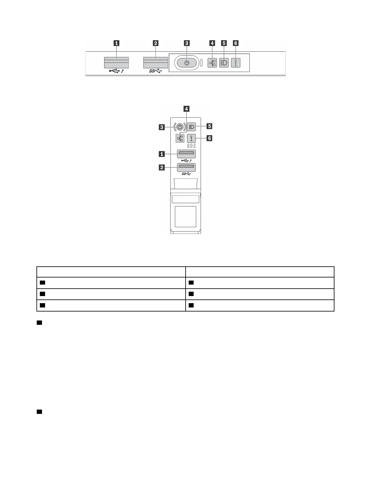
Figure 10. Front I/O assembly for server models with eight 3.5-inch-drive bays, eight 2.5-inch-drive bays, and sixteen 2.5-
inch-drive bays
Figure 11. Front I/O assembly for server models with twelve 3.5-inch-drive bays and twenty-four 2.5-inch-drive bays
Table 3. Components on the front I/O assembly
Callout Callout
1 XClarity Controller USB connector 2 USB 3.0 connector
3 Power button with power status LED 4 Network activity LED
5 System ID button with system ID LED 6 System error LED
1 XClarity Controller USB connector
Depending on the setting, this connector supports USB 2.0 function, XClarity Controller management
function, or both.
• If the connector is set for USB 2.0 function, you can attach a device that requires a USB 2.0 connection,
such as a keyboard, a mouse, or a USB storage device.
• If the connector is set for XClarity Controller management function, you can attach a mobile device
installed with the application to run XClarity Controller event logs.
• If the connector is set to have both functions, you can press the system ID button for three seconds to
switch between the two functions.
2 USB 3.0 connector
Used to attach a device that requires a USB 2.0 or 3.0 connection, such as a keyboard, a mouse, or a USB
storage device.
16
ThinkSystem SR650 Maintenance Manual
 Loading...


