11 Diagnoscs and fault eliminaon
This secon contains informaon on error handling, drive diagnoscs and fault analysis.
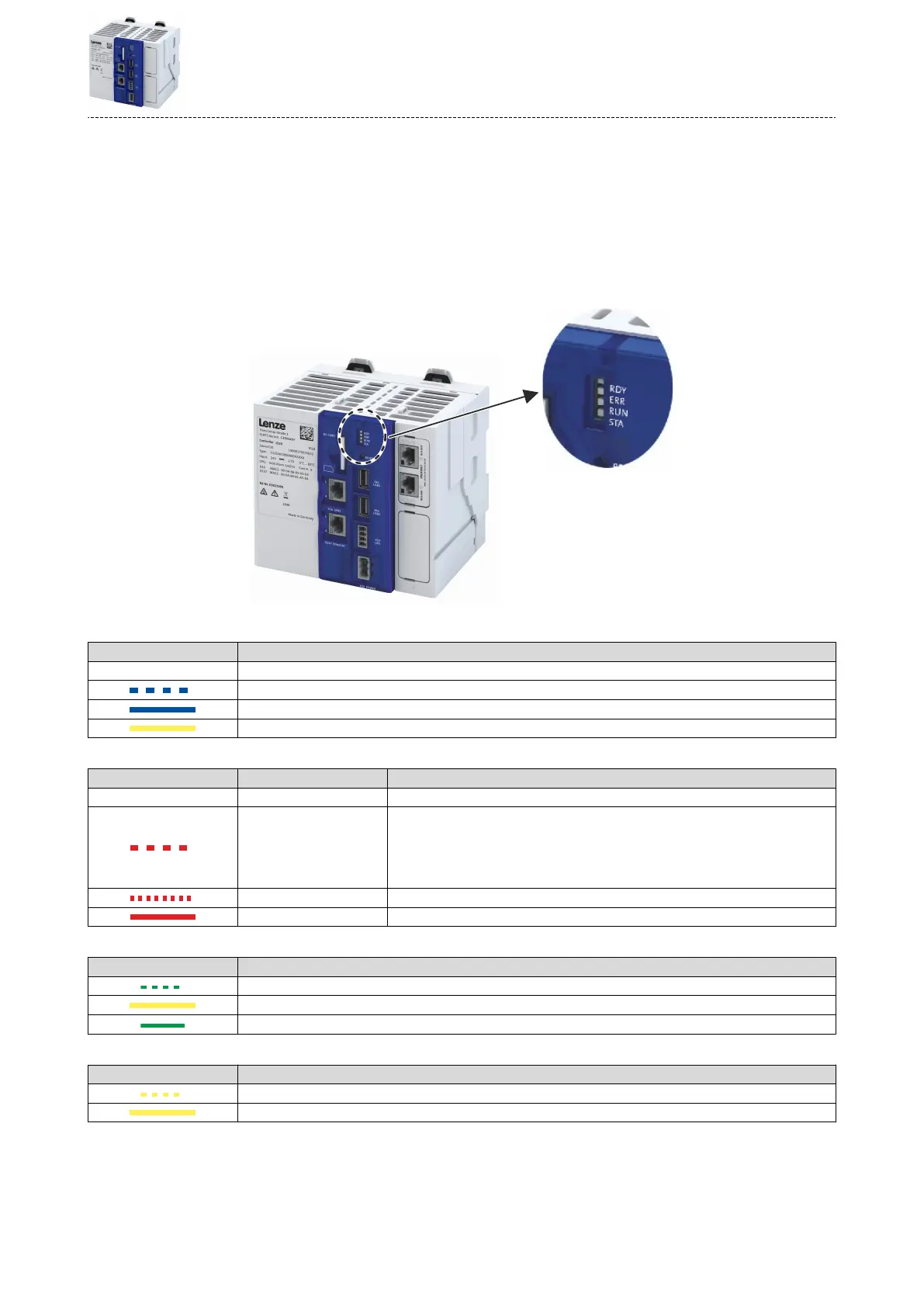
11.1 LED status display
The controllers are equipped with LEDs indicang the current operang status. Depending on
the running soware applicaon, dierent control modes of the LEDs are possible.
LED status display
"RDY" LED (blue/yellow) Meaning
O Device is switched o.
Device is starng up.
Device is ready for operaon.
Voltage is underrun.
LED status display
"ERR" LED (red) Status Meaning
O NO REACTION There are no acve error responses in the device.
WARNING The device indicates a warning. The funcon of the device diers from the expected
behavior.
Note!
If the "RDY” LED is blinking at the same me, a hardware error of the device has
occurred.
TROUBLE The device indicates a fault. The funcon of the device is impaired.
ERROR The device indicates an error. The funcon of the device is faulty.
LED status display
"RUN" LED (yellow/green) Meaning
PLC project is being loaded.
PLC project is stopped.
PLC project is started.
LED status display
"STA" LED (yellow/green) Meaning
Update/Downgrade process is running.
Update/Downgrade process is carried out.
Diagnoscs and fault eliminaon
LED status display
93