Lenze · E94AYCEO communication module (EtherNet/IP™) · Communication Manual · DMS 3.0 EN · 12/2013 · TD17 76
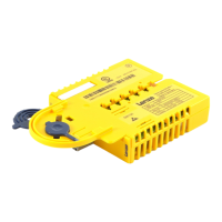
11 Diagnostics
11.1 LED status displays
_ _ _ _ _ _ _ _ _ _ _ _ _ _ _ _ _ _ _ _ _ _ _ _ _ _ _ _ _ _ _ _ _ _ _ _ _ _ _ _ _ _ _ _ _ _ _ _ _ _ _ _ _ _ _ _ _ _ _ _ _ _ _ _
11 Diagnostics
The LEDs on the front of the communication module serve to diagnose faults. Moreover, the
»Engineer« serves to show diagnostic information.
11.1 LED status displays
The following status displays are distinguished:
• Module status displays
( 77)
• CIP™ status displays
( 78)
• Status displays on the RJ45 sockets (X233, X234)
( 80)
Note!
LED status displays for trouble-free operation:
• The LEDs ST
( 77) and NS ( 78) are permanently on.
• The green LEDs on the X233 and X234 RJ45 sockets are lit, and the yellow LEDs are
blinking or jittering
( 80).