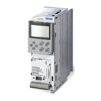
9300 Servo PLC
Appendix
3-6
l
ServoPLC EN 2.0
No. RemedyCauseMeaningDisplay
053 OH3 Motor temperature higher
than fixed limit temperature
• For temperate detection via
• Motor too hot because of impermissibly high
currents
• Frequent and too long acceleration
Check drive dimensioning
reso
ver or
ncremen
a
encoder
No PTC connected Connect PTC or switch off monitoring (C0583=3)
054 OH4 Heat sink temperature higher
than variable limit temperature
(C0122)
Ambient temperature T
amb
>40°Cor50°C • Allow controller to cool and ensure better
ventilation
• Check ambient temperature in the control
cabinet
Heat sink very dirty Clean the heat sink
Incorrect mounting position Change the mounting position
Value set under C0122 too low Enter higher value under C0122
057 OH7 Motor temperature higher
than variable limit temperature
(C0121)
• Motor too hot because of impermissibly high
currents
• Frequent and too long acceleration
Check drive dimensioning
• For
empera
ede
ec
ion via
No PTC connected Connect PTC or switch off monitoring (C0584=3)
encoder
Value set under C0121 too low Enter higher value under C0121
058 OH8 Motor temperature via inputs
T1/T2 too high
• Motor too hot because of impermissibly high
currents
• Frequent and too long acceleration
Check drive dimensioning
Terminals T1, T2 are not assigned Connect PTC or thermostat or switch off monito-
ring (C0585=3)
061 CE0 Communication error
AIF module óBasic unit
Interference during transfer of control commands
via automation interface (AIF)
Plug in automa tion module firmly, bolt down, if
necessary
062 CE1 Communication error CAN1_IN
CANx_IN receives faulty data or communication
• Check cable at X4
063 CE2 Communication error CAN2_IN
in
errup
ed
• Check transmitter
•
064 CE3 Communication error CAN3_IN
,
C0357/x
065 CE4 CAN BUS-OFF status
(too many faulty telegrams re-
ceived)
PLC has received too man y faulty telegrams send
via system bus and has disconnected itself from
the bus
• Check wiring
• Check bus termination (if any)
• Check screen contact of the cables
• Check PE connection
• Check bus load
• Reduce baud rate (observe cable length)
066 CE5 CAN time-out
(gateway function)
For tele-parameterisation via system bus (C0370):
• Slave does not respond
• Communication monitoring time exceeded
• Check wiring of the system bus
• Check system bus configuration
070 U15 Undervoltage of internal 15 V
voltage supply
Check voltage supply for Drive PLC
071 CCR Internal fault The program sequence of the processor was inter-
fered.
• Shield control and motor cables as necessary
• Check PE wiring and PE connections
072 PR1 Check sum error
in parameter set 1
CAUTION:
Default setting is loaded auto-
matically!
• Error while reading a parameter set
• Interruption of parameter set transfer via
keypad (e.g. by disconnection of the keypad)
• Set the desired parameters and save them
under C0003
• For PRO the supply voltage must be switched
off additionally
• Check use of pointers
The saved parameters do not match the loaded
software version
Before an error can be acknowledged, the para-
meter set must be manually saved under C0003
074 PEr Program e rror Error detected in program • Check use of pointers
• Send controller with parameter set and PLC
program (on diskette) to Lenze
075 PR0 General error
in parameter sets
CAUTION:
Default setting is loaded auto-
matically!
See Cause & Remedy, no. 072 (PR1)
079 PI Error during
parameter initialisation
• Error detected during parameter transfer
between two controllers
• Parameter set does not match the PLC or
controller (e.g. data transfer from a
high-performance control ler to a
lower-performance controller)
• Correct the parameter set
• Check code initialisation values
efesotomasyon.com - Lenze

 Loading...


