Device parameters and interfaces
62 BPS 34 Leuze electronic
Output data
None
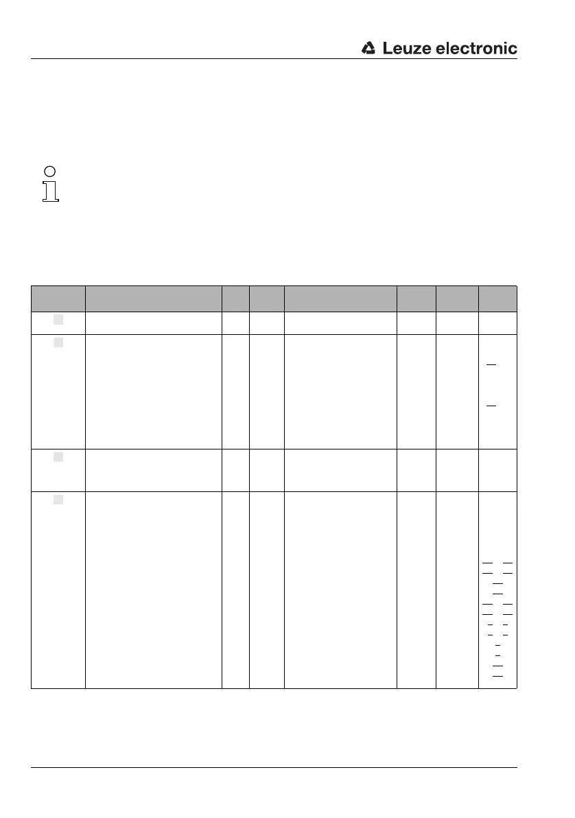
8.1.7.8 Module 8: Switching output
Note!
Underlined in the CR column are the modules which must be activated in addition to the cur-
rent module.
Description
The module defines the mode of operation of the digital switching output.
Parameters
Parameter Description Rel.
addr.
Data
type
Value range Default Unit CR to
module
Bias level
The parameter defines the bias
level of the switching output.
0
unsign
8
0: LOW (0V)
1: HIGH (+U
B
)
0 ––
Selection
of the
speed limit
value
Defines whether the switching
output is controlled by
static speed limit value 1,
static speed limit value 2,
static speed limit value 3,
static speed limit value 4
or the
dynamic speed limit value
1.0
1.1
1.2
1.3
1.4
Bits
For each
0: No
1: Yes
0
0
0
0
0
–
25
for
static
26
for
dynami
c
Pulse dura-
tion in [ms]
The parameter defines the
switch-on time period for the
switching output. If the value is 0,
the signal is static.
2
unsign
16
0 … 1,300 400 ms –
Switch-on
function
[EF]
The parameter specifies the
events which set the switching
output:
- speed valid
- speed not valid
- position limit value 1 reached
- position limit value 1 not
reached
- outside measurement range
- within measurement range
- position limit value 2 reached
- position limit value 2 not
reached
- erroneous measurement
- successful measurement
- PROFIBUS pos. edge
- PROFIBUS neg. edge
- speed limit value reached
- speed limit value not reached
4.0
4.1
4.2
4.3
4.4
4.5
4.6
4.7
5.2
5.3
5.4
5.5
5.6
5.7
Bits
For each
0: Not active
1: Active
0
0
0
0
0
0
0
0
1
0
0
0
0
0
–
22
22
14
+ 16
14 + 16
10
10
15 + 17
15 + 17
1 + 9
1 + 9
8
8
25
25