Display elements
20 SOLID-2 Leuze electronic
Review-Stand, , 8. April 2015
DEUTSCH ENGLISH FRANÇAIS ITALIANO ESPAÑOL NEDERLANDS
4.2.2.3 Receiver Extended, LED displays and protective field states when the internal
start/restart interlock function is activated:
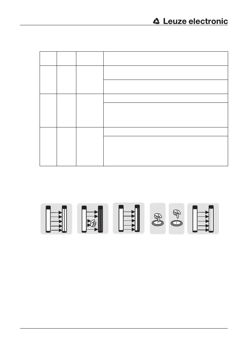
The following illustrations show the behaviour of the LEDs and OSSDs in start/restart
interlock operating mode.
LED1 LED2 Protective
field
Meaning
green OFF free LED1
green
= OSSDs safety outputs in the ON state
LED2 OFF = Start/restart interlock not active, see Fig.
4.2-2 a
red OFF interrupted LED1 red = OSSDs safety outputs in the OFF state
LED2 OFF = Start/restart interlock not active.
As long as the protective field is interrup-
ted, it is not possible to start/restart the de-
vice, see Fig. 4.2-2 b
red yellow free LED1 red = OSSDs safety outputs in the OFF state
LED2
yellow
= Start/restart interlock active. The OSSDs
safety outputs are only turned on again af
-
ter pressing and releasing the start/restart
button in a time window of 300 ms to 5 s,
see Fig. 4.2-2 c-e
Table 4.2-5: Receiver Extended with selected internal start/restart interlock function
a b c d e
LED1: green
LED2: OFF
OSSDs: ON
LED1: red
LED2: OFF
OSSDs: OFF
LED1: red
LED2: yellow
OSSDs: OFF
LED1: green
LED2: OFF
OSSDs: ON
Fig. 4.2-2: Start/restart interlock function after intrusion into the protective field