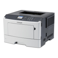
Do you have a question about the Lexmark MS510 Series and is the answer not in the manual?
| Print Technology | Monochrome Laser |
|---|---|
| Print Speed | Up to 45 ppm |
| Print Resolution | 1200 x 1200 dpi |
| Processor Speed | 800 MHz |
| Memory | 256 MB |
| Standard Output Capacity | 250 sheets |
| Connectivity | USB 2.0, Gigabit Ethernet |
| Operating System Compatibility | Windows, Mac OS, Linux |
| Media Types Supported | Card stock, Envelopes, Labels, Plain Paper, Transparencies |
| Media Sizes Supported | A4, A5, A6, Legal, Letter |
| Dimensions | 15.7 x 15.4 in. |
| Weight | 14.1 kg |
| Duplex Printing | Automatic |
Information regarding laser safety compliance and product classification for safe operation.
General safety guidelines, warnings, and precautions for product use and maintenance.
Warning about potential injury from lithium battery replacement hazards.
Overview of the printer, including general description and special tools.
Explains symbols and statements used in the service manual for clarity and safety.
Guidance on selecting and using paper and specialty media for optimal print quality.
Information about printer memory types, data storage, and data erasure procedures.
Lists essential tools needed for performing service and maintenance tasks on the printer.
Initial steps and checks for troubleshooting printer problems before deeper diagnosis.
Explains various printer messages, error codes, and their corresponding actions.
Guides on resolving common print quality problems and performing initial checks.
Lists specific print quality issues and provides checks to diagnose them.
Explains how to avoid paper jams and understand jam messages.
Lists error codes related to 200 paper jam messages and their corresponding actions.
Steps to diagnose issues related to static jams detected by the input sensor.
Diagnoses issues with input sensors that detect early or late paper arrival.
Troubleshooting steps for input sensors related to image jam detection.
Diagnoses jams related to the main drive motor control system.
Specific error codes and actions for 201 paper jams.
Diagnoses jams detected by the narrow media sensor.
Lists error codes for 202 paper jams and their resolution steps.
Troubleshooting steps for jams detected by the fuser exit sensor.
Actions to resolve 230 paper jams, specifically related to duplex clearing.
Details error codes for 23y.xx paper jams and related duplex service checks.
Steps to diagnose and fix issues with the printer's duplexing mechanism.
Procedures for clearing 240 paper jams occurring in specific trays.
Lists error codes for 24y.xx paper jams and indicates service check procedures.
Details error codes for 242.xx paper jams, referring to option tray service checks.
Lists error codes for 243.xx paper jams and points to option tray service checks.
Details error codes for 244.xx paper jams, directing to option tray service checks.
Troubleshooting steps for paper jams specifically occurring in Tray 1.
Diagnoses paper jams occurring in optional printer trays.
Procedures for clearing paper jams in the multipurpose feeder.
Lists error codes for 25y.xx paper jams and refers to MPF service checks.
Troubleshooting steps for issues related to the Multipurpose Feeder (MPF) assembly.
Lists user attendance messages and error codes with corresponding actions.
Lists various printer hardware errors and their corresponding actions.
Specific error codes prefixed with '1xx' related to printer hardware.
Troubleshooting steps for issues related to the Laser Scanning Unit (LSU).
Diagnostic steps for resolving problems with the printer's fuser unit.
Troubleshooting steps for the Low Voltage Power Supply (LVPS).
Diagnoses issues with the toner density sensor and its related components.
Troubleshooting steps for the Capacitance Toner Level Sensing (CTLS) system.
Diagnoses issues with the main drive gearbox and its motor.
Troubleshooting steps for the Autocompensator Mechanism (ACM) assembly.
Diagnoses problems related to the cartridge gearbox and its gears.
Troubleshooting for the pick/lift motor gearbox in Tray 1.
Diagnoses issues related to the printer's cooling fan.
Lists various 9xx error codes and their corresponding troubleshooting actions.
Troubleshooting steps for general system software errors and communication problems.
Lists hardware errors specific to printer input options and trays.
Specific error codes prefixed with '3xx' related to input option hardware.
Troubleshooting steps for pick/lift motor gearbox issues in option trays.
Diagnoses issues with separator/passthrough motors in option trays.
Troubleshooting steps for Autocompensator Mechanism (ACM) motors in option trays.
Diagnoses problems with the controller card for option trays.
Lists common printer symptoms and directs to corresponding service checks.
Troubleshooting steps when the printer shows no signs of power or activity.
Steps to diagnose issues with the printer's controller board.
Diagnoses problems with the printer's control panel buttons.
Steps to diagnose issues with the printer's control panel display and functionality.
Troubleshooting steps for errors related to toner supply or cartridge issues.
Diagnoses problems with printing via USB connection.
Troubleshooting steps for network connectivity and communication issues.
Explains the control panel layout and menu navigation for MS510dn/MS610dn models.
Explains the meaning of different indicator and sleep button light colors and patterns.
Describes the control panel and menu structure for the MS610de model.
Explains the printer's home screen interface and its interactive elements.
Details how to use the touch-screen interface for printer functions.
Provides a categorized list of all available menus within the printer's settings.
Introduces the diagnostics menu group for servicing and manufacturing.
Steps to access the printer's diagnostics menu for advanced functions.
Explains how to adjust printer margins for proper print registration.
Describes tests to verify printer output using various paper sources.
Allows viewing printer settings and testing output quality.
Overview of hardware tests to diagnose printer component failures.
Verifies the functionality of the control panel display.
Tests the functionality of all control panel buttons except the sleep button.
Checks the validity of DRAM, both standard and optional, for errors.
Tests USB ports in High-Speed mode to diagnose connectivity issues.
Verifies and adjusts the printer's duplexing mechanism for correct operation.
Performs a quick test to check duplex top margin settings.
Adjusts the offset for the top margin in duplex printing.
Adjusts the left margin position for duplexed pages.
Verifies the proper operation of duplex sensors and switches.
Tests feeding paper into the duplex unit from Tray 1.
Tests the paper feeding mechanism for all installed input trays.
Feeds blank pages through the paper path to test feed mechanisms.
Verifies the functionality of input tray sensors.
Verifies media feeding into specific output bins.
Verifies the functionality of output bin sensors.
Checks the correct operation of primary internal sensors like input, exit, and door sensors.
Runs tests on internal device components like disk and flash memory.
Performs a non-destructive read/write test on the printer's disk drive.
Tests and cleans the printer's disk drive, potentially erasing data.
Verifies the condition of the flash memory by writing and reading data.
Allows configuration of printer settings and defaults for optimal operation.
Resets printer settings to factory defaults, supporting US or non-US values.
Displays the printer's usage count based on print tests.
Shows the total number of pages printed by the printer.
Displays the unique identifier for the printer's controller board processor.
Settings used by engine code ECs to resolve field problems.
Shifts margins to print to the physical edge of supported paper sizes.
Adjusts factory settings for strobe sampling to determine parallel port data validity.
Resets printer settings in EP Setup to factory defaults to fix print quality issues.
Adjusts fuser temperature to solve paper curl or letterhead melting issues.
Controls the transfer roll algorithm for optimal toner transfer.
Adjusts the developer voltage offset to control print contrast.
Controls the charge roll voltage for proper toner charging.
Adjusts the gap between sheets to reduce curl and stacking problems.
Optimizes toner usage by calibrating sensors and adjusting darkness.
Prints a report of current configuration menu settings and their values.
Displays a log of events and messages that occurred during printer operation.
Prints a report containing detailed diagnostic information from the event log.
Removes all current information from the Event log.
Exits the diagnostics menu and restarts the printer in normal mode.
Allows configuration of printer settings and operations for optimal performance.
Steps to access the printer's configuration menu for advanced functions.
Displays the current value of the maintenance kit counter, tracking printer usage.
Resets the maintenance counter after installing a new maintenance kit.
Limited version of print quality pages setting for testing output.
Prints a list of configuration menu settings and their values.
Generates a printed report of events detailed in the print log.
Enables or disables the control panel menus for user access.
Controls whether the printer recognizes and uses the PPDS data stream.
Manages download emulators, enabling or disabling them.
Restores printer settings to factory defaults, affecting network or base settings.
Controls power saving modes, including Sleep Mode settings.
Controls prompts for paper size changes based on sensed media.
Manages prompts for envelope size changes based on sensed media.
Determines how the printer handles paper/envelope change prompts, with user intervention options.
Manages buffered jobs stored on the hard disk, allowing deletion.
Controls whether data written to the hard disk is encrypted.
Wipes the printer's hard disk, erasing all stored data including fonts and macros.
Makes sensitive information on storage devices indecipherable via NVRAM reset.
Creates microscopic holes in text to save toner by reducing overlapping toner.
Adjusts high-frequency screens for printed font data.
Reduces throughput to solve paper curl problems, activated as a last resort.
Sets Standby Mode to On or Off for power saving.
Determines paper orientation for A5 paper based on long or short edge feed.
Enables external developers to test application stability against the printer.
Sets the delay before a repeating key starts repeating on the control panel.
Sets the number of key presses per second for repeating keys on the control panel.
Resets supply usage history to factory shipped levels.
Erases user-defined strings for custom messages.
Sets the throughput for the printer's USB port (Auto or Full speed).
Configures the panel to automatically display printer-related IR after inactivity.
Adjusts USB driver mode for PC chipset compatibility.
Puts the printer into a mode for loading correct code or updating firmware.
Allows booting the printer from a secondary set of instructions for code flashing.
Navigates to network settings for fine-tuning communication parameters.
Provides access to advanced settings under the guidance of technical support.
Instructions on how to access the SE menu via a web browser.
Lists top-level and intermediate menus for the Service Engineer menu.
Key tips to follow before starting part removal and replacement procedures.
Information about printer memory types and data storage, and how to erase data.
Instructions to prevent damage to electronic parts from electrostatic discharge.
Procedure for replacing the RIP board and operator panel when both fail.
Steps to back up eSF solutions and settings before replacing the RIP board.
Information on ribbon cable connectors, including ZIF types and precautions.
Details types of ZIF connectors and care needed during insertion/removal.
Instructions for removing and inserting cables into horizontal top contact connectors.
Step-by-step guide for correctly inserting cables into horizontal top contact connectors.
Instructions for removing and inserting cables into horizontal bottom contact connectors.
Step-by-step guide for correctly inserting cables into horizontal bottom contact connectors.
Instructions for removing and inserting cables into vertical mount contact connectors.
Step-by-step guide for correctly inserting cables into vertical mount contact connectors.
Instructions for removing and inserting cables into horizontal sliding contact connectors.
Step-by-step guide for correctly inserting cables into horizontal sliding contact connectors.
Instructions for removing and inserting cables into Low Insertion Force (LIF) connectors.
Step-by-step guide for correctly inserting cables into LIF connectors.
Procedure for mechanically adjusting the printhead position after removal.
Procedure for electronically aligning the printhead after mechanical adjustment.
Procedures for removing components located on the left side of the printer.
Step-by-step instructions for removing the left printer cover.
Instructions for removing the main drive gearbox assembly.
Procedure for removing the Multipurpose Feeder (MPF) solenoid.
Instructions for removing the MPF gearbox assembly.
Procedure for removing the reverse solenoid component.
Instructions for removing the cartridge gearbox assembly.
Steps for removing the duplex gear assembly from the printer.
Procedures for removing components located on the right side of the printer.
Step-by-step instructions for removing the right printer cover.
Procedure for removing the tray present sensor.
Instructions for removing the cooling fan duct.
Procedures for removing cooling fans from the printer.
Instructions for removing the cooling fan mount assembly.
Steps to remove the controller board shield on MS610de models.
Instructions for removing the printer's controller board.
Procedure for removing the toner cartridge smart chip contact.
Procedures for removing components located on the front of the printer.
Instructions for removing the left front mount assembly.
Instructions for removing the right front mount assembly.
Steps for removing the transfer roll, with important handling precautions.
Procedure for removing the cartridge plunger component.
Procedures for removing printer bezels from various models.
Instructions for removing printer nameplates from different models.
Procedures for removing the control panel assembly from the printer.
Instructions for removing the UICC component from the printer.
Procedure for removing the control panel USB port on MS610dn models.
Procedure for removing speaker and USB port from MS610de control panel.
Instructions for removing the Multipurpose Feeder (MPF) assembly.
Steps for removing the MPF pick roller cover.
Procedure for removing the MPF pick roller.
Steps for removing the bail component.
Instructions for removing the jam access cover.
Procedure for removing the printer's front door.
Steps for removing the front access cover.
Procedure for removing the front door sensor.
Instructions for removing the front input guide.
Steps for removing the separator pad component.
Procedures for removing components located at the bottom of the printer.
Steps for removing the main power supply unit.
Specific instructions for removing the power supply on MS610 models.
Instructions for removing the power supply shield.
Steps for removing the duplex unit assembly.
Procedures for removing duplex and input sensors.
Steps for removing the index sensor component.
Procedure for removing the media present sensor.
Steps for removing the toner density sensor.
Procedure for removing the trailing edge sensor component.
Steps for removing the Autocompensator Mechanism (ACM) assembly.
Instructions for removing the pick/lift motor gearbox assembly.
Procedures for removing components located on the rear side of the printer.
Steps for removing the printer's dust cover.
Procedure for removing the rear door and cover.
Procedure for removing the narrow media/bin full sensor.
Steps for removing the redrive assembly.
Instructions for removing the printer's fuser unit.
Procedures for removing components located on the top side of the printer.
Steps for removing the printer's top cover.
Procedure for removing the Laser Scanning Unit (LSU).
Procedures for removing 250/550-sheet optional paper trays.
Steps for removing the pick roller assembly.
Procedure for removing the separator roll assembly.
Steps for removing the Autocompensator Mechanism (ACM) assembly.
Diagrams showing the location of external printer components.
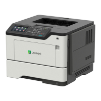
Illustrates external component locations for MS510dn and MS610dn models.
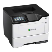
Shows the front view of the printer with numbered external parts.
Shows the rear view of the printer with numbered external ports and controls.
Illustrates external component locations for the MS610de model.
Shows the front view of the MS610de with numbered external parts.
Shows the rear view of the MS610de with numbered external ports and controls.
A guide to inspecting parts at specific intervals for damage, cleaning, or replacement.
Information on scheduled maintenance intervals and necessary maintenance kits.
Lists part numbers and contents for various maintenance kits for different models.
Instructions to reset the maintenance counter after replacing a maintenance kit.
Guidelines for lubricating printer parts, specifying approved lubricants.
Steps for safely cleaning the printer's exterior and interior components.
Explains column headings and abbreviations used in the parts catalog.
Exploded view and part list for printer covers.
Exploded view and part list for electronic components (Part 1).
Exploded view and part list for electronic components (Part 2).
Exploded view and part list for printer frame components.
Exploded view and part list for optional paper trays.
Lists part numbers and contents for various maintenance kits.
Lists part numbers for power cords specific to different regions.
Documents power consumption characteristics of the printer in various operating modes.
Details electrical requirements for low-voltage and high-voltage printer models.
Specifies recommended clearances around the printer for proper operation.
Provides sound level measurements conforming to ISO standards.
Lists acoustic and operating environment specifications for MS510 models.
Lists acoustic and operating environment specifications for MS610 models.
Defines environmental conditions for printer operation, storage, and shipping.
Lists internal hardware options like memory, hard disk, and network interfaces.
Describes available media handling components such as output bins and trays.
Explains the Power-On Reset sequence and hardware integrity tests.
Details the printer's processor functions for RIP, engine, and NVRAM management.
Describes component functions for feeding media from trays.
Explains the functions of sensors and motors for input tray media feeding.
Explains the MPF's drive mechanism, sensors, and paper feeding process.
Describes the process of single-sided printing, including deskewing and toner transfer.
Explains the media path and solenoid activation for printing on the second side.
Details the function of key media handling components like gearboxes and rollers.
Explains how the main drive gearbox transfers power to various printer mechanisms.
Describes the ACM's function in picking and feeding media accurately.
Identifies and describes the function of various sensors in the printer.
Diagram showing sensor locations for MS310/MS410 models.
Diagram showing sensor locations for MS510/MS610 models.
Detects media trailing edge and aids in paper size sensing.
Detects the presence of media within the Multipurpose Feeder (MPF) tray.
Detects the presence of media within the paper tray.
Detects if a paper tray is inserted into the printer.
Detects if the standard bin is full by monitoring an actuator.
Detects toner density by measuring a pre-placed toner patch on the drum.
Detects media from option trays, triggering the next pick roller action.
Detects toner level in the imaging unit and triggers toner replenishment.
Safety switch cutting power to LSU when the front door is opened.
Discharges air to prevent excessive temperature increase within the printer.
Explains the HVPS and LVPS sections and their voltage outputs.
Controls printing operations via communication with RIP and peripherals.
Diagram illustrating roller placement for MS310/MS410 models.
Diagram illustrating roller placement for MS510/MS610 models.
Explains the EP process, focusing on the printhead scanning and image creation.
Describes the printhead components and how the laser scans the drum for image creation.
Explains the charge step where the photoconductor is uniformly charged.
Describes the expose step where the laser creates a latent image on the drum.
Explains the develop step where toner adheres to the latent image.
Describes the transfer step where toner is moved from the drum to the paper.
Explains the clean step where residual toner is removed from the photoconductor.
A list of acronyms used in the manual and their definitions.