17 300781172_002_C0 - 01/2019 - © Leybold
Buttons and connections
3 Buttons and connections
3.1 Front panel buttons and displays
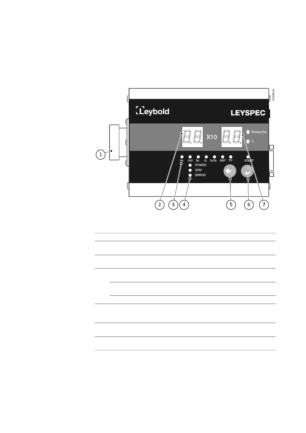
Fig. 3.1 Front panel
Item Description
1 Analyzer tube connector For connection to the analyzer tube.
2 Measurement value/fault display Shows measured partial pressure value. For
faults, displays the error code.
3 Gas species/total pressure display
LED
Displays the gas species and total pressure
being measured.
4 POWER POWER LED (green) comes on when power
is applied.
SEM Secondary Electron Multiplier (SEM) LED
(green) comes on when SEM is used.
ERROR ERROR LED (red) comes on if a fault occurs.
5 Gas species/total pressure
selection button (CH)
Select the gas species you want to measure
or total pressure. The orange LED shows the
current selection.
6 Measurement start button (START) Starts measurement. The upper orange LED
indicates that measurement has started.
7 Measurement value units display
LED
The unit of measured partial pressure. For
O
2
/N
2
the display shows a percentage (%).