57 300781172_002_C0 - 01/2019 - © Leybold
Maintenance
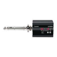
6. Install a new SEM. Put the socket onto pins "l" and "m" (A).
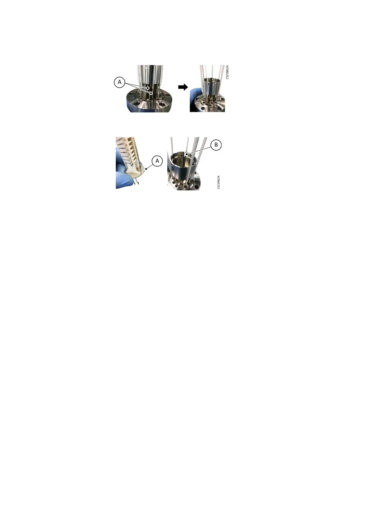
7. Set the cylinder (A) in the original position. Fix it with four M2 screws (B).
8. Set the wiring of RF1 and RF2 to Q-Pole in the original position. Fix it with two
M2 screws.
9. Install the FIL1, FIL2, FIL.C, GRID, FOCUS and GAUGE wiring to the ion source.
10.Bind the two bands and fix them with M2 screws.
11.Check continuity and insulation referring to
Refer to these lists when disposing
or recycling.
on page 72.
11.3 Calibrate
To operate the RGA in normal condition, periodical calibration or tuning is needed.
We recommend that you calibrate at fixed intervals.
11.3.1 Tuning RF matching
Procedure:
1. Check that the pressure is less than 1 x 10
-2
Pa.
2. Connect a circuit tester to the TUNING socket on the back of the unit and set
the tester to DC voltage mode.
Purpose: To output the RF voltage efficiently, RF matching between the control and
the sensor is needed. RF matching shifts according to ambient conditions
or if the sensor is contaminated. If the shift becomes large, an RF error can
occur.
Cycle: Tune when you exchange the sensor, or if ambient conditions
(temperature, humidity) change.