19 300781172_002_C0 - 01/2019 - © Leybold
Buttons and connections
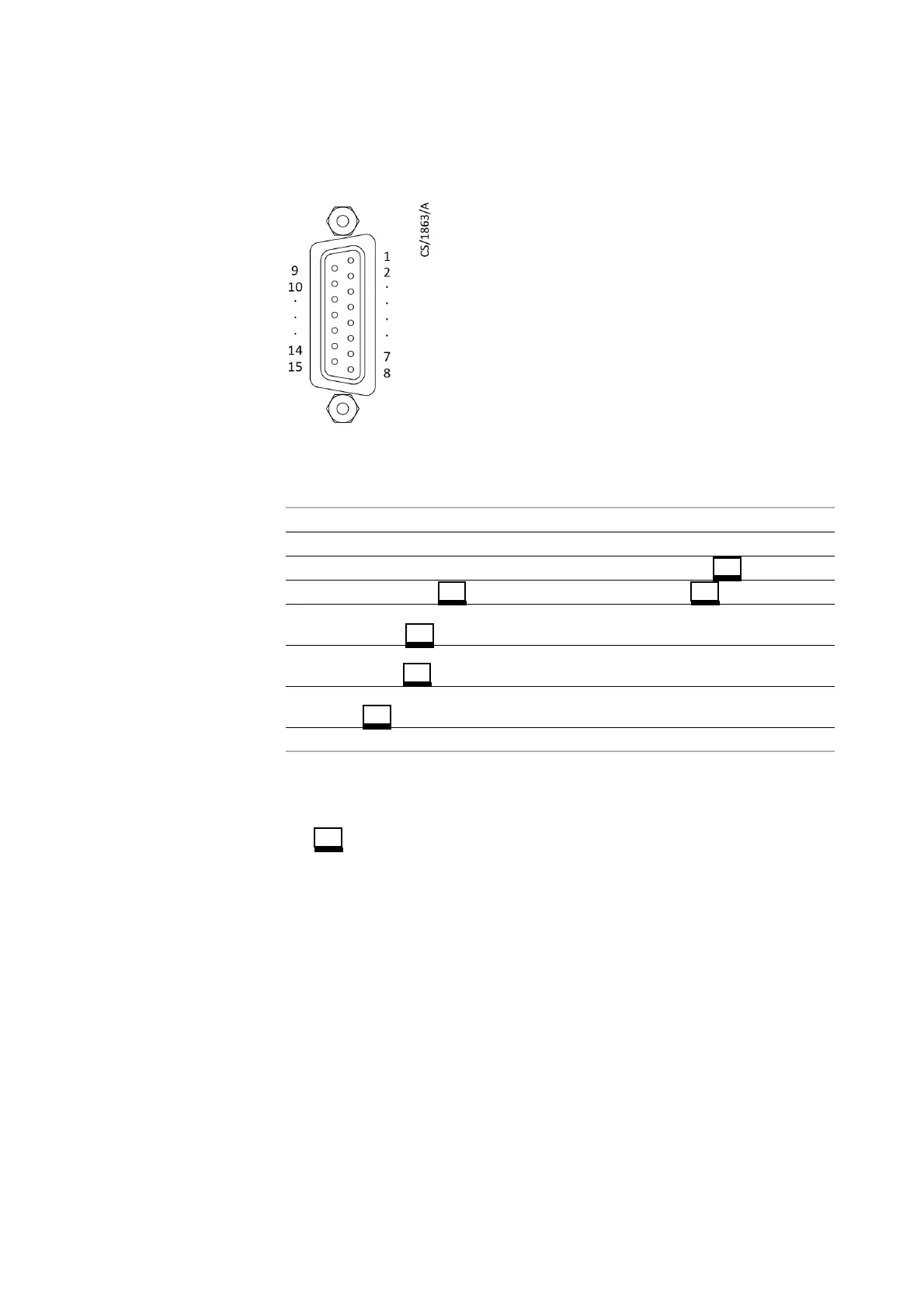
3.3 EXT-I/O connector
Fig. 3.3 I/O pin connector assignment
Digital output common is pin 8.
Digital input common is pin 13.
in the signal identification shows that the signal is LOW (short, negative
logic).
Total pressure set-point output, partial pressure abnormal output and partial
pressure alarm output of terminals 5-7 are effective only when software is
connected.
START input of terminal 11 is effective only in the local mode.
To connect another recorder or device in parallel with the RGA's analogue input,
use a resistor (input impedance) of about 100 k
Ω in series with the RGA analogue
input line (terminal numbers: 1 and 2). Analogue input impedance of the RGA is
about 50k
Ω when power is on. When the power supply is switched to OFF, the
input impedance is undefined (several
Ω) because power is not supplied to the
input operational amplifier. If another recorder is connected in parallel with the
RGA's analogue input, the input voltage to that recorder may fluctuate due to this
undefined impedance.
Terminal
No.
Signal identification
Termina
l No.
Signal identification
1 Analogue input 1 (INPUT) 9 A-GND (INPUT)
2 Analogue input 2 (INPUT) 10 A-GND (INPUT)
3 11 START input ON/OFF (INPUT)
4 Error output OK/NG (OUTPUT) 12 Interlock ON/OFF (INPUT)
5 Total pressure (TP) set-point
output ON/OFF (OUTPUT)
13 INPUT COM (INPUT)
6 Partial pressure abnormal
output ON/OFF (OUTPUT)
14
7 Partial pressure alarm output
ON/OFF (OUTPUT)
15
8 OUTPUT-COM (OUTPUT)