35 300781172_002_C0 - 01/2019 - © Leybold
External inputs and outputs (I/O)
8 External inputs and outputs (I/O)
External interface signals connect to the EXT-I/O connector on the rear panel.
8.1 Pressure and error outputs
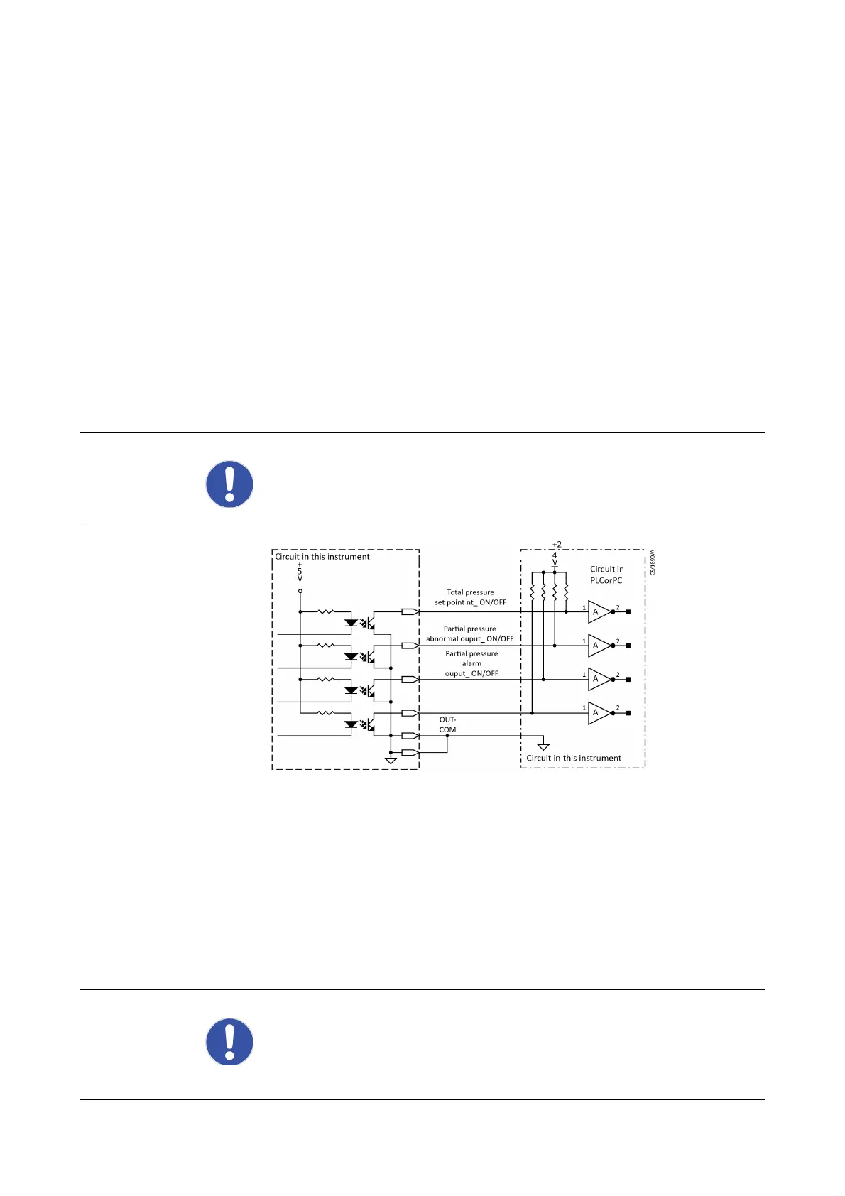
The outputs for total pressure set-point, partial pressure fault, partial pressure
warning, and error output are provided as digital signals (negative logic).
The output format is open collector with a common emitter. The capacity of the
transistor is maximum 24 V between the collector and emitter, the maximum current
of the collector is 50 mA, and the rated loss power is 1 V.
The error output is set high when there is any error with the filament, secondary
electron multiplier (SEM) and RF and set low in the normal state.
Fig. 8.1 Digital output internal circuit diagram
8.2 Interlock input
The interlock input is used to protect the filament, secondary electron multiplier
(SEM) and RF power supply using an external signal.
Ground the interlock input terminal (pin 12) and INPUT-COM terminal (pin 13) with
the relay contact or open collector. The maximum permissible leakage current from
the external unit is 0.1 mA or less. Maximum saturation voltage between emitter and
collector is 0.4 V.
NOTICE:
The total pressure set-point output, partial pressure abnormal output and
partial pressure warning output are effective only when the dedicated gas
analysis software is connected.
NOTICE:
When the unit is in its error state, the error LED lights red. The unit keeps its
interlock error state until the error is confirmed by the dedicated gas analysis
software. This means that even when the interlock signal is not active, the interlock
may be displayed as an error.