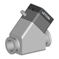
4. Pass the electrical cable through the cable gland and connect to the4.
appropriate terminals. Tighten the earth (ground) terminal connection
to a torque of 2.13 to 2.87Nm. Refer to
. Refer to for correct
wiring convention.
5. Tighten the dome shaped nut on the cable gland until the outer sheath5.
of the cable is rmly gripped. Using a tool, tighten to a torque of 2.5Nm.
Do not overtightened.
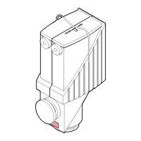
6. Ret the terminal box to the pump housing using the 4 off M5 screws6.
torqued to 3 Nm.
7. Ret the fan cowl to the pump by rst inserting the fan connector into7.
the mating half in the terminal box and securing the cowl using the 2 off
M5 screws torqued to 3 Nm.
The correct wiring convention for a positive electrical phase rotation
(clockwise phase sequence) is as follows:
Table 9. Wiring convention
Customer's supply 3-phase Electric terminal box
L1 L1
L2 L2
L3 L3
Disconnect from electrical supply
Befor
e removing the physical electrical supply connection to the pump,
isolate the mains input supply.
Voltage conguration 3-phase pump
▪ For low voltage operation, dened as 200 V
, 50 Hz and 200-230 V
,▪
60Hz, the wiring must be congured as shown in
.
▪ 3-phase pump will be delivered congured for high voltage operation,▪
dened as 380-415 V, 50 Hz and 460 V, 60 Hz, and wired as shown in
.
34 300668736_002_C7 - © Leybold
Installation