Installation
31
300554859_002_C0 - 11/2016 - © Leybold
A-A
A-A
A A
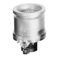
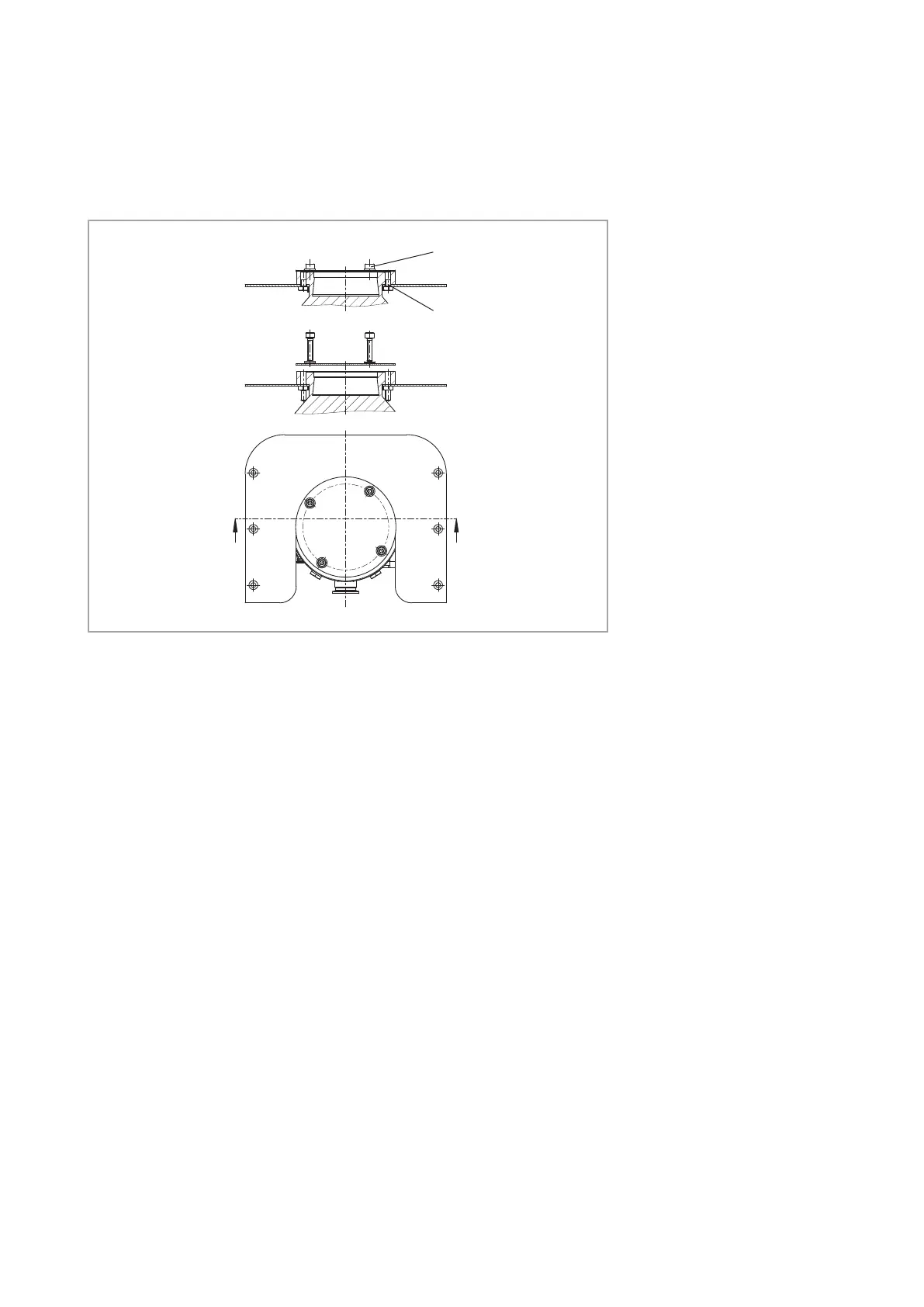
Fig. 3.6 Transport lock ot the CF pump systems TURBOLAB 350 / 450
Transport lock
Threaded pin
CF pump systems TURBOLAB 350 / 450
The TURBOVAC is no longer secured once the transport screw has been
removed.
Ensure therefore, immediately after removing the transport protection, that a
vacuum vessel or pipe connection is immediately connected to the HV flange
and installation plate.
The TURBOVAC is equipped with two threaded pins to prevent falling, but
nevertheless allow the pump to be lifted out. The threaded pins can be
removed in either direction by turning the Allen screws, without lifting at the
pump.
All pump systems
Pay attention to maximum cleanliness when connecting.
The TURBOVAC generates little noise or vibration. The TURBOVAC must not
be influenced by vibration from other machinery.
Foreign objects which enter the pump via the high vacuum connection can
cause serious damage to the rotor. An inlet screen must therefore be fitted.
The TURBOVAC is precision balanced and is generally operated without a
reson ance damper. To decouple extremely sensitive equipment and to pre-
vent transfer of external vibrations to the pump a special resonance damper
is available for mounting at the high-vacuum flange.
Artisan Technology Group - Quality Instrumentation ... Guaranteed | (888) 88-SOURCE | www.artisantg.com
 Loading...