Operation
45
300554859_002_C0 - 11/2016 - © Leybold
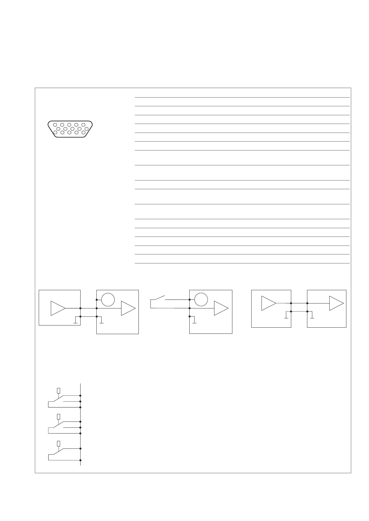
Fig. 4.1 REMOTE interface X1
Pin Name Description
1 Error relay (com)
2 Error relay (n.c.)
3 Normal operation relay (n.o.)
4 Normal operation relay (com)
5 Normal operation relay (n.c.)
6 Signal GND
7 High level output 24 V, 100 mA, Tolerance acc. to
device supply voltage
8 Start input (High) High > 10 V ± 0,5 V
Reset input (Low) Low < 7.5 V ± 0,5 V
9 Error relay (n.o.)
10 Standby input High > 10 V ± 0.5 V
Low < 7.5 V ± 0.5 V
11 Cooling/Venting valve High > 10 V ± 0.5 V
input (Low) Low < 7.5 V ± 0.5 V
12 Analog output (Default: Frequency) 0 ... 10 V, 2 mA
13 Analog GND
14 Warning relay (n.c.)
15 Warning relay (com)
Shield Connected with pump housing
24 V
7
8
6
0 V = STOP/Fehlerreset
24 V = START
24 V
7
8
6
24 V
5 V
1k8Ω
3k3Ω
7
8
6
Steuerung
Kontakt offen = STOP//Fehlerreset
Kontakt geschlossen = START
5
3
4
n. c.
n. o.
com.
2
9
1
n. c.
n. o.
com.
Frequenzwandler
Frequenzwandler
14
15
n. c.
com.
11
15
610
REMOTE X1
15-pole Sub-D female
High Density
24 V
7
8
6
0 V = STOP/Fehlerreset
24 V = START
24 V
7
8
6
Steuerung
Kontakt offen = STOP//Fehlerreset
Kontakt geschlossen = START
5
3
4
n. c.
n. o.
com.
2
9
1
n. c.
n. o.
com.
Frequenz-
wandler
Frequenz-
wandler
12
13
Analog-Ausgang
Steuerung
Frequenz-
wandler
Start/Stop input
Pin 10
0 V = no Standby operation
24 V = Standby operation
Pin 11
0 V = no function
24 V = Cooling or valve is activated
Pin 10
Contact open: no Standby operation
Contact closed: Standby operation
Pin 11
Contact open: no function
Contact closed: Cooling or valve is activated
24 V
7
8
6
0 V = STOP/Fehlerreset
24 V = START
24 V
7
8
6
24 V
5 V
1k8Ω
3k3Ω
7
8
6
Steuerung
Kontakt offen = STOP//Fehlerreset
Kontakt geschlossen = START
5
3
4
n. c.
n. o.
com.
2
9
1
n. c.
n. o.
com.
Frequenzwandler
Frequenzwandler
14
15
n. c.
com.
Relay
Normal operation relay
4 and 5 connected (normal position) Run-down, run-up, stop
4 and 3 connected Normal operation
Error relay
1 and 2 connected (normal position) No error
1 and 9 connected Error
Warning relay
14 and 15 connected (normal position) No warning
14 and 15 open Warning
Analog output
Maintain pin 6 Signal
GND and pin 13 Analog
GND separate so as to
avoid equalisation cur-
rents.
Contact open = STOP/Error reset
Contact closed = START
0V = STOP/Error reset
24 V = START
Frequency
converter
Controller
Frequency
converter
Controller
Frequency
converter
Relay functions
see Section 4.4.3
Functions of the analog output
see next page
Artisan Technology Group - Quality Instrumentation ... Guaranteed | (888) 88-SOURCE | www.artisantg.com
 Loading...