05
PRODUCT CONFIGURATION AND INSTALLATION OF REMOTE CONTROLLER
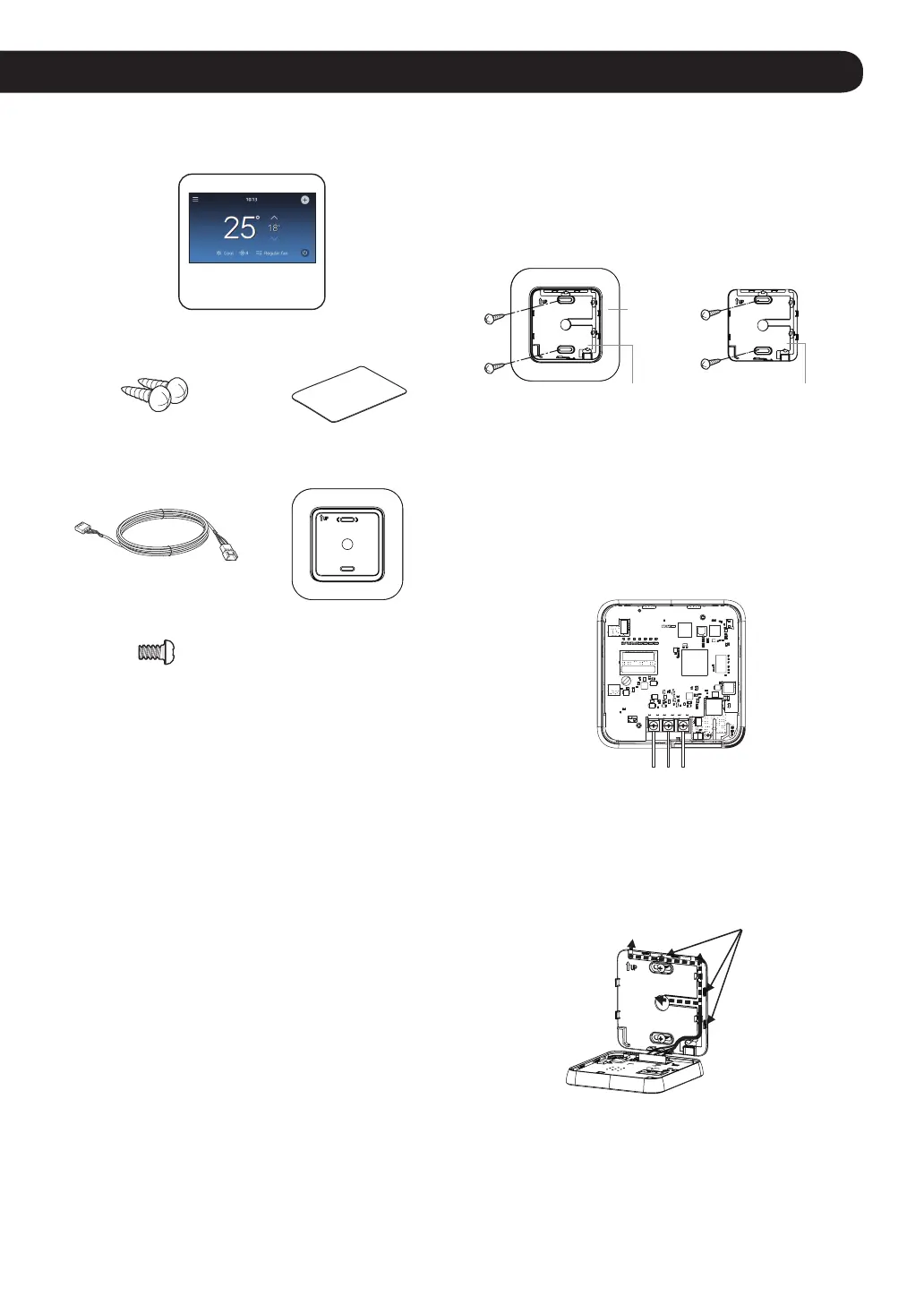
Product Configuration
Remote controller
Remote controller
fixing screws (2EA)
OWNER’S &
INSTALLATION MANUAL
Connecting wire (1 EA) Wall plate
Top and Back cover
screws(1EA)
Installation of Remote Controller
Follow the below guidelines for installing the remote
controller.
NOTE
• During wired remote controller installation, do not embed
inside the wall. (It may cause temperature sensor failure.)
Do not install the cable over 50 m. (It may cause
communication defects.)
• When installing the extension cable, carefully check the
direction of the connectors on the remote controller side
and the product side before the installation.
• Extension cable specification: Use AWG 24, 3 conductor
equivalent or higher wired cables.
• Do not install cables longer than 50 m, as this may cause
communication problems.
• Install the product so that it doesn’t bend or cause a
clearance with the wall.
• Incorrect wiring can cause damage to the product.
• To avoid damage by static electricity, touch the metal
parts before handling the remote controller to discharge
the static electricity from the body.
* 10 m Cable model: PCW-QE10A
1
Pull the cable from the wall and check the cable
direction to install.
2
Align the back cover (installation plate) and check the
positions of two mounting holes on the wall.
3
Fix the back cover on the installation position through
the mounting holes by using screws.
W
all
pla
te
or
Back Cover
(Installation Plate)
Back Cover
(Installation Plate)
NOTE
• Depending on your environment, you can install the
remote controller neatly by placing the wall plate on the
wall and tightening the back cover.
4
Connect the power cable to the terminal at the bottom
of the remote controller as shown in the gure below.
GND / SIG / 12V
5
Place the lower part of the remote controller under the
back cover, and x the power cable to the back cover
hook as shown in the gure below to the place where
the power cable will come out of the back cover.
Hook
(Figure.1)