LGMG North America Inc.
Operation and Safety Manual
15
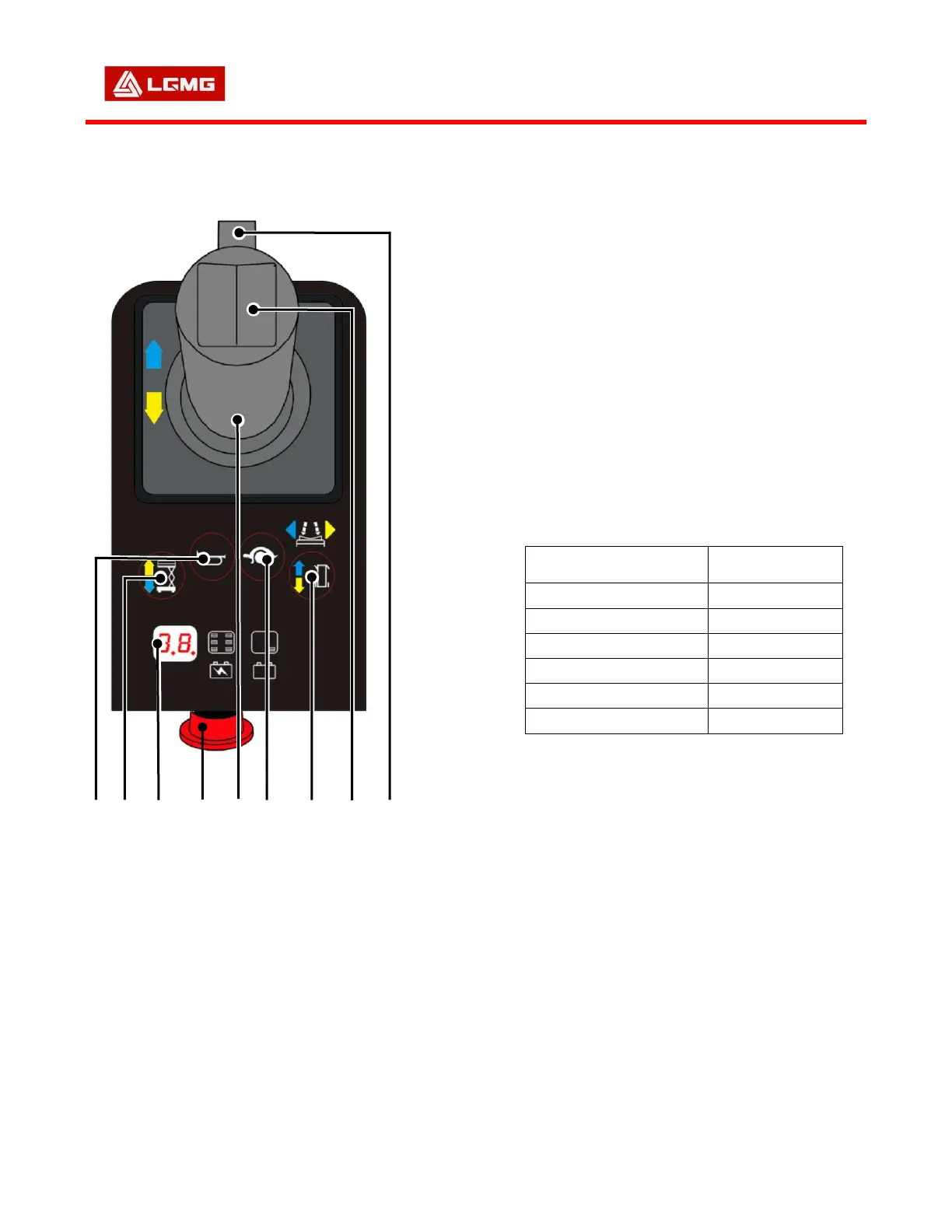
3.2 Platform Controls
Fig-3.1(If equipped)
1. Horn B utton
2. Lift S witch
3. Displa y
4. Eme r g e ncy St op S w i tc h
5. Contr o l Lever
6. D r ive Spee d B u t ton
7. D r ive Fu ncti o n Button
8. S t e er Swi tc h
9. E n a bling Sw i t c h
3.2.1 Horn Button
The horn will sound when this button is pressed,
and will stop when the button is released.
3.2.2 Lift Switch
Pressing this switch activates the lift function for
the platform.
3.2.3 Display
The Display shows Diagnostic Fault Codes and
when charging the batteries, displays charging
status.
Table 4-Data on the Display
3.2.4 Emergency Stop Switch
The power supply to the machine is disconnected
when the emergency stop switch is pressed.
△
! Notice
An emergency stop switch is installed
on both the chassis and the platform
controller. The switches operate
together in series. Operation can be
performed when both switches are
pulled out. The power supply will be cut
off when either emergency stop switch
 Loading...