Chapter 3 Electrical Installation 21
Liebert CRV+ Series Air Conditioner User Manual
76
75
71 62
70 61
38GND
371 2V
24
B2
51
A2
64
63
TB3
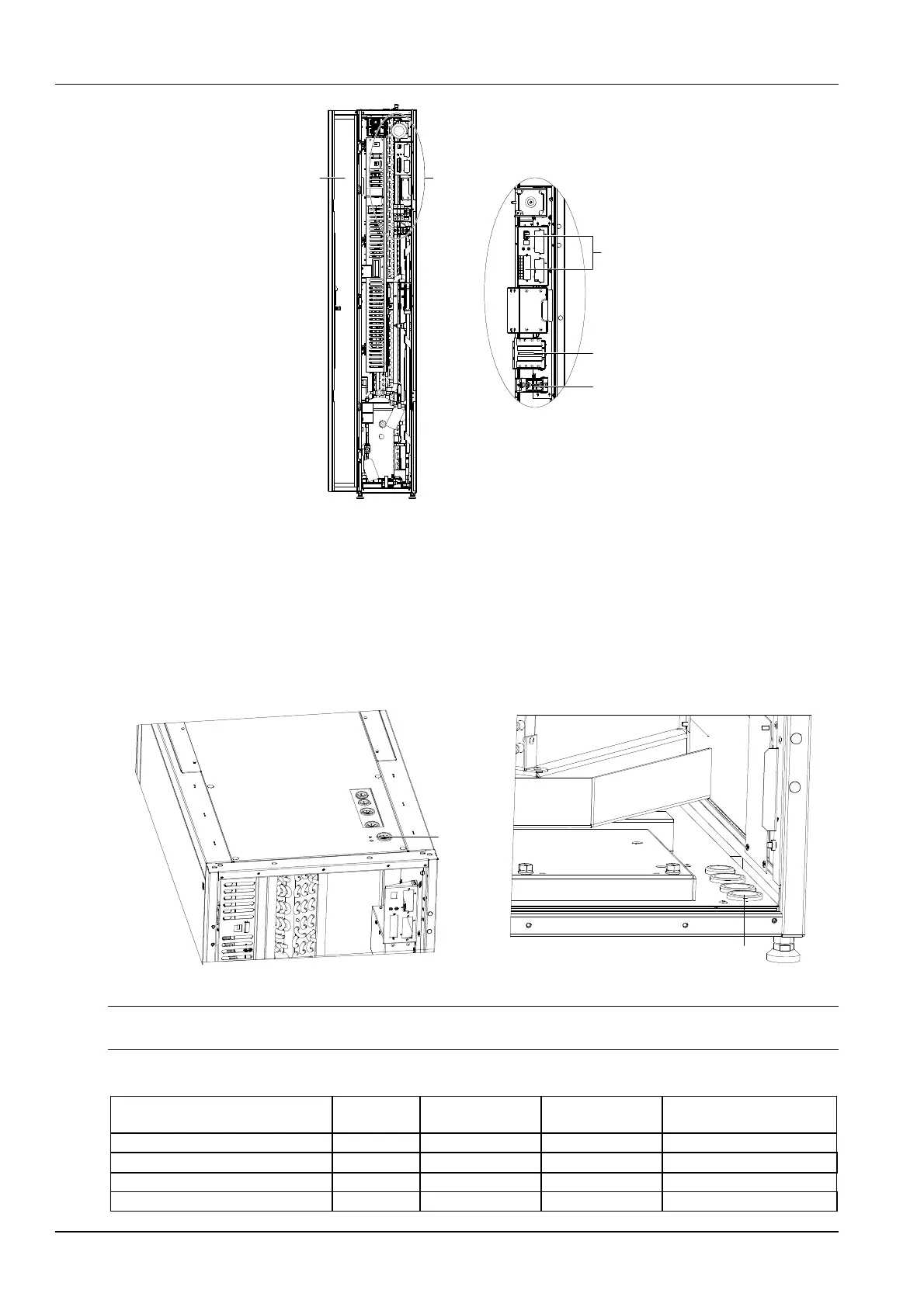
ABack door
A amplified
Connecting
control cables
Main MCB
Cable clamp
Figure 3-1 Unit electrical control box and cable connection (open the back door 120
°
)
3.2.2 Connecting Power Cable Of Indoor Unit
The specific location of power port of indoor unit is shown in Figure 3-1. Connect terminals L1 ~ L3, N, and PE to
their counterparts of external power supply respectively.
Fix the input cables to the cable clamp, which is located on the inner side panel of the unit, as shown in Figure 3-1.
For the cable specification, see the rated full-load current (FLA) listed in Table 3-1.
The top cable entry hole and bottom cable entry hole are shown in Figure 3-2.
Bottom cable entry hole
Top cable
entry hole
Figure 3-2 Top cable entry hole and bottom cable entry hole
Note
The cable sizes should meet the local wiring regulations.
Table 3-1 Full-load current (unit: A)
Model
Standard
model
Standard model
with electric heater
Standard model
with humidifier
Standard model with electric
heater and humidifier
CR025HA1380S02E10000PV000 24.86 24.86 26 26
CR025RA138SS12E10000PV000 26 \ \ \
CR035HA1380S02E10000PV000 31.6 46.6 42.3 46.6
CR035RA138SS12E10000PV000 46.6 \ \ \