14 Chapter 2 Mechanical Installation
Liebert CRV+ Series Air Conditioner User Manual
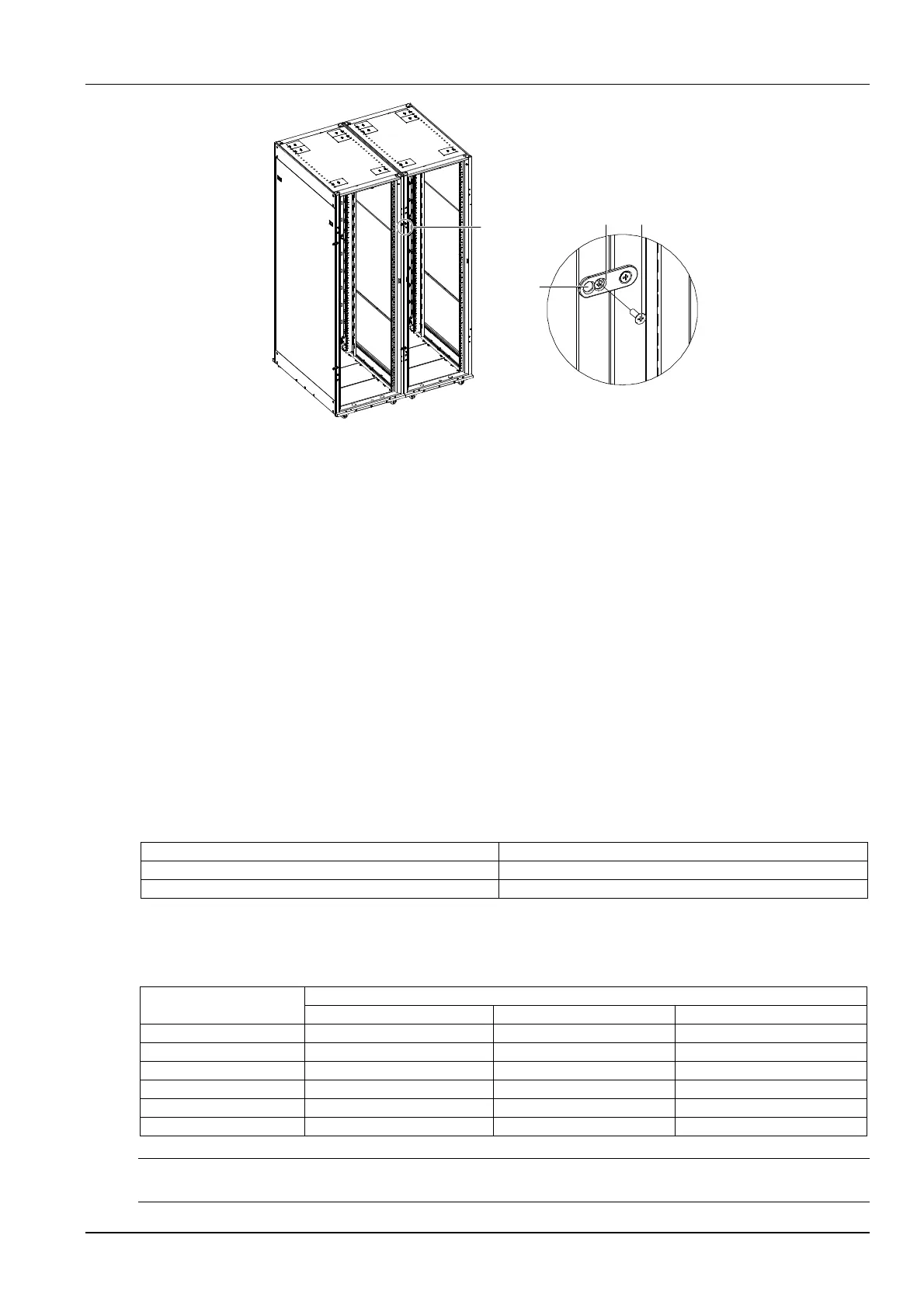
A
A amplified
Cabinet connector
Installation
hole
M5 countersunk
head screw
Figure 2-16 Schematic diagram for connecting the cabinet
3. Install the other three cabinet connectors according to the same method.
2.5 Piping
2.5.1 Connecting Air-Cooled Unit Pipe
All joints of the cooling pipes must be silver-brazed. Standard industry procedures must be followed in selecting,
laying, and fixing the pipes, and vacuuming the system and charging refrigerant. Take pipeline pressure drop, oil
return to the compressor and minimization of noise and vibration into consideration during design and construction.
General
The recommended pipe sizes are ‘equivalent lengths’ (see Table 2-6 for equivalent lengths of partial components),
with the resistance caused by bends taken into account. The installer should confirm that the sizes are appropriate for
the site conditions.
1. If the one-way equivalent length exceeds 30m, or if the vertical distance between indoor unit and outdoor unit
exceeds the values in Table 2-5, consult Emerson before the installation to confirm whether a pipe extension kit is
needed.
Table 2-5 Vertical distance between indoor unit and outdoor unit
Relative position Value
Outdoor unit higher than indoor unit Max.: +30m
Outdoor unit lower than indoor unit Max.: -8m
2. The pipe sizes recommended in Table 2-6 are ‘equivalent lengths’, with the resistance caused by bends and valves
taken into account. The installer should confirm that the sizes are appropriate for the site conditions.
Table 2-6 Equivalent lengths of partial components
Outer Diameter (OD) of
liquid pipe (inch)
Equivalent length (m)
90° bend 45° bend T type three-way
3/8 0.21 0.10 0.76
1/2 0.24 0.12 0.76
5/8 0.27 0.15 0.76
3/4 0.3 0.18 0.76
7/8 0.44 0.24 1.1
1-1/8 0.56 0.3 1.4
Note
A trap should be installed for every 7.5m of vertical distance. Please consult Emerson for details.