English
6
Notes:
S both the alarm and the warning must be reset manually on
the Microface.
S An alarm causes the unit to stop and the unit in stand---by
(if available) to intervene. If the unit is in stand---alone, the
high and low pressure alarms don’t stop the machine to al-
low the operation in Freecooling mode in the proper condi-
tions.
S The warning doesn’t cause the unit to stop.
S In case the safety heater thermostat intervenes, the reset
must be carried out on the thermostat, following the same
instructions as before.
5.3.4 -- Optional al arm bo ard
Besides the components described for the standard configura-
tion, on the alarm card --- which can be supplied as optional ---
there are relay contacts tohave thefollowing alarmsseparated:
1) Compressor high and low pressure
2) High temperature
3) Low temperature
4) Dirty filter alarm (if installed)
5) Fan fault
These alarms cause the unit to stop in the same ways as de-
scribed in the previous paragraph. For a complete description
ofthealarmsseetheencl.Microfacemanual.
5.3.5 -- Unit in stand--by
The control of the units in stand---by is completely automatic,
thanks to the possibility of connecting the Microface control. A unit
in stand---by starts in case an alarm stops the main unit; this oc-
curs even if the main unit is switched off or disappears from the
system, due to a fault on the control connect ing bus.
The rotatio n of the units in stand---by occurs automatically every
24 hours, so as to allow a homogeneous wear of the system com-
ponents. If the system is connected to the Hiromatic interface, it is
possi ble to set a different rotation contro l. If several units are simul-
taneously working with the same set point, the temperature used
for the contr ol is the average of the detect ed ones; further, in the
operation with compressor, the proportional band is divided in as
many parts as twice the number of units belonging to the system,
so as to shut the total available refrigerati ng capacity. The opera-
tion in the Freecooling mode is homogeneous and simultaneous
on all units.
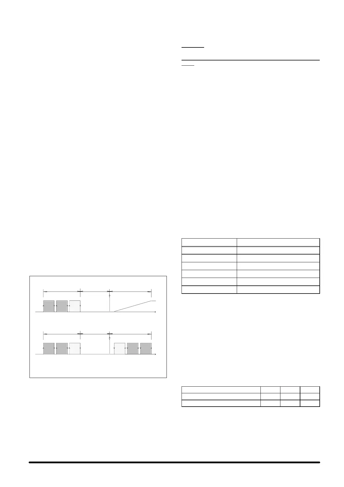
The Fig. L), shown as an example, describes the operation of a
system consist ing of 3 units.
1 = main unit
2 = unit in stand--- by
3 = unit in stand--- by
Set °CCoolingHeating
F reecooling mode
3
Compressor cooling mode
11
223
Dead band!P@ Pband !P@ Pband
Set °CCoolingHeating
3
1
2
Dead band!P@ Pband !P@ Pband
F i g . L --- A s y s t e m c o n s i s t i n g o f 3 u n i t s , 2 o f w h i c h i n s t a n d --- b y ---
Microface control
6 --- R22 units refrigerant
charge
CAUTION: THESE OPERATIONS MUST BE PERFORMED
B Y AN EXPERT TECHNICIAN.
THE UNIT, AS SUPPLIED, IS PRECHARGED WITH
NITRO-
GEN.
6.1 --- Charac te risti cs of the refri g erant
fluid R22
At standard temperature and pressure it is a colourless gas
with low toxicity, non---flammable, and it has an allowed expo-
sure limit value (AEL/TLV) corresponding to 1000 ppm (aver-
age value measured on 8 hours per day). In the event of leak-
age, air the room before use.
6.2 --- Refrigerant charge R22
WHEN REPAIRING THE REFRIGERATION CIRCUIT,
PLEASE COLLECT ALL REFRIGERANT IN A CONTAINER:
DO NOT DISPOSE OF IT IN THE ENVIRONMENT.
1) After connecting the refrigerating lines to the main paths of
the valves, placed on the evaporating and motor condens-
ing units, discharge the precharged nitrogen by operating
on the ¼” SAE tap, with needle valve, of the motor con-
densing unit.
2) Empty the circuit with the special (quality) vacuum pump,
applying a vacuum of 0.7 absolute mbar.
3) After 3 hours check not to have exceeded 1.3 absolute
mbar. If the vacuum is not kept there are leaks. Repair the
circuit and repeat the operations from point 2.
4) Connect the charge cylinder to the liquid line of the motor
condensing and start charging the amount of refrigerant
R22 as shown in Tab. C.
Tab. C -- Refrigerating charge R22 for a 5 m dis-
tance between the evaporating and mo-
tor condensing units.
MODEL Refrigerating charge R22 (kg)
Hisp SE+SC05 2.2
Hisp SE+SC06 2.5
Hisp SE+SC08 4.3
Hisp SE+SC10 4.4
Hisp SE+SC13 4.4
Hisp SE+SC14 4.4
5) In case it is impossible to complete charging shift the cylin-
der mode to compressor intake and complete charging or
however, after charging, operate as follows:
6) Start up the unit as shown in par. 3.2.
7) Start the compressor manually.
8) Guarantee a constant condensation temperature (prefer-
ably 50°C); if necessary, partially obstruct the condenser
exchange surface to obtain these conditions.
9) W aituntil the operating conditions of the wholerefrigeration
circuit are normal.
10) Make sure, while the system is in standard operation, that
the superheating co mplies with following values (Tab. D:
manometric temperatures are shown).
Tab. D -- R22: Superheating table
Internal temperature °C 24 27
Internal relative humidity %RH 50 50
Compresor superheating °C 8 12
Va lues applying with condensation T = 50
°
C
For refrigerating line distances between 5 and 15 m, increase
the charge of the circuit as shown in the following Tab. E.