18 Chapter 3 Electrical Installation
Liebert NXC 30kVA And 40kVA UPS User Manual
Connection terminal and cable routing method
Figure 3-2 shows the UPS power cable connection terminals. Figure 3-3 and Figure 3-4 show the power cable entry
and routing methods.
Note
1. The power cables should be routed through tunnels or cable troughs to prevent cable damage due to mechanical stress.
2. When routing the cables inside the cabinets, it is required to bind and fix the cables as instructed in Figure 3-3 and Figure 3-4 in
the cabinets, so as to prevent cable damage due to mechanical stress.
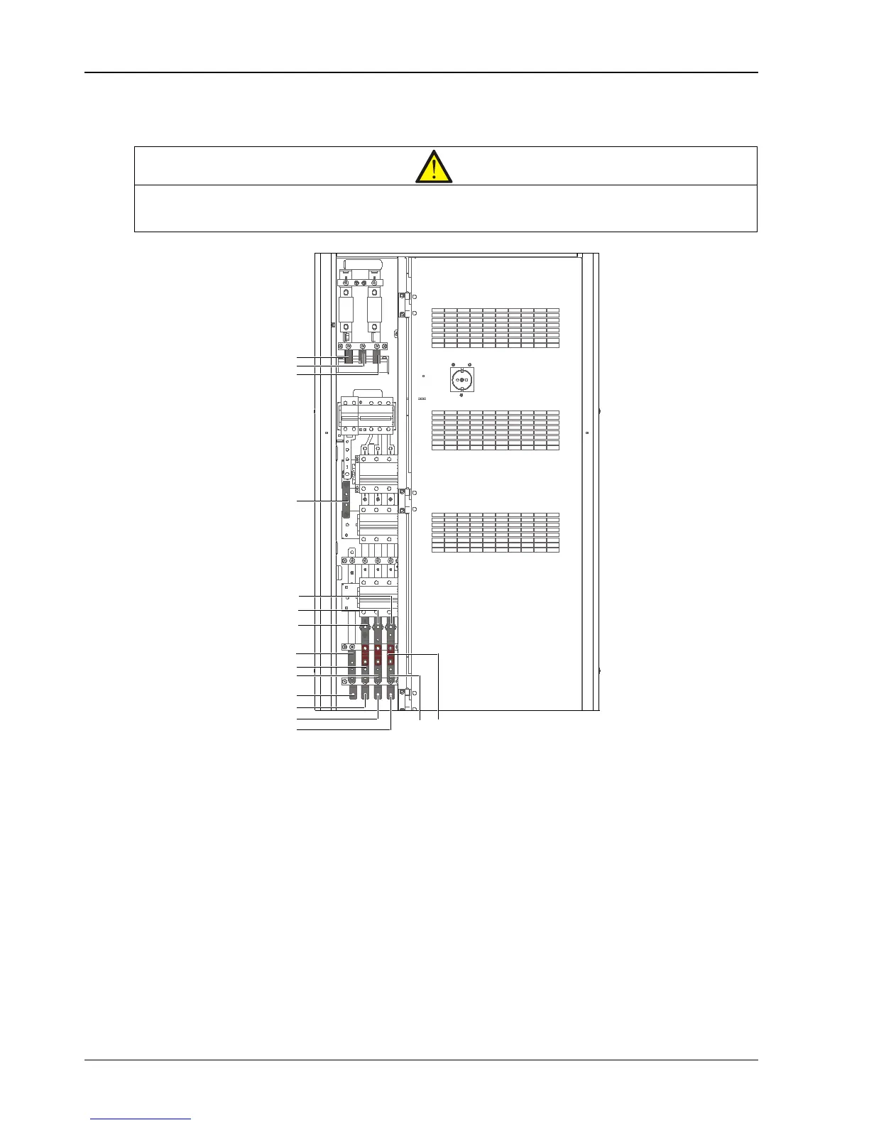
Figure 3-2 Power cable connection terminals
+
N
-
PE
mA
mB
mC
N
bA
bB
bC
oN
oA
oB
oC
Note:
1. +, -, N: battery input terminals
2. PE: PE input terminal
3. mA, mB, mC: rectifier input terminals
4. bA, bB, bC, N: bypass input terminals
5. oA, oB, oC, oN: output terminals
Shorting copper bar of
common input configuration