LCDBBCIG03Sept08
CHELSEA DIGITAL SWITCH INSTALLATION GUIDE 122
These instructions supersede the instructions on the side
of the shipping box for any field-programmed Chelsea
DigitalSwitches
™
.
PREPARATION
Record the serial number of the Chelsea Digital-1.
Switch
™
onto the System Device Schedule located in
the door of the Master Blue Box. You will need this
later for startup and programming.
Device Type
Location
Serial #
Address
Device Type
Location
Serial #
Address
Device Type
Location
Serial #
Address
Device Type
Location
Serial #
Address
Device Type
Location
Serial #
Address
Device Type
Location
Serial #
Address
Device Type
Location
Serial #
Address
Device Type
Location
Serial #
Address
Device Type
Location
Serial #
Address
Device Type
Location
Serial #
Address
Device Type
Location
Serial #
Address
Device Type
Location
Serial #
Address
Device Type
Location
Serial #
Address
Device Type
Location
Serial #
Address
Device Type
Location
Serial #
Address
Device Type
Location
Serial #
Address
SYSTEM DEVICE SCHEDULE: (for Master Panels)
LIGHTING CONTROL & DESIGN
905 Allen Ave s Glendale, CA 91201s Support 800-345-4448 s www.lightingcontrols.com
(Master) LCP1
1
L
BB Panel Schedule.indd 4 8/13/2008 1:37:47 PM
3 btn sw
Hallway
8875
6 btn sw
lobby
4685
DI-6
LCP 1
4055
7
LCP 2
telecom
af97
5
(Master) LCP1
elec rm
ce80
1
Note the serial number and device type on the back of the
SYSTEM DEVICE SCHEDULE.
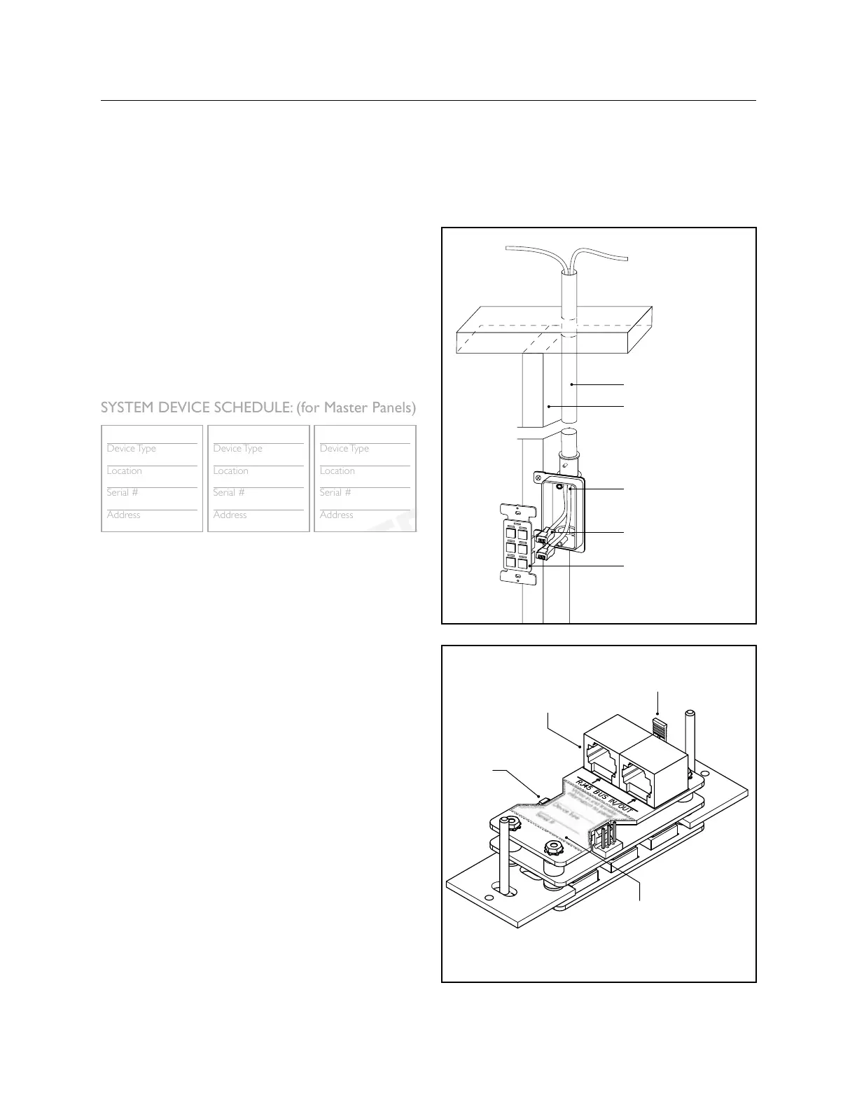
CONNECTION
Run Cat. 5 to the low voltage ring or switch box. 2.
Daisy-chain devices using Cat. 5 with RJ45s
*
.
Once cables have been properly tested3.
*
, connect
them to the RJ45 sockets on the back of the Chelsea
DigitalSwitch
™
.
MOUNTING
Mount the Chelsea DigitalSwitch4.
™
like any standard
decorator style switch. It fits in any standard Decora-
tor style wall plate (provided by the installer).
PROGRAMMING & COMMISSIONING
Once the system has been powered up5.
*
begin switch
button programming per the programming section of
The Blue Box “O&M Manual”.
Once programmed, exercise each button on each 6.
switch several times to ensure that it is operating per
customer requirements.
CHELSEA INSTALLATION INSTRUCTIONS
FOR FIELD-PROGRAMMED SWITCHES
* Refer to The Blue Box LT “System Start-Up & Cabling Guide”.
Terminator: installed on
bus end devices only.
RJ45 sockets for
digital bus.
Serial Number Label
Note: serial number on the
System Device Schedule.
Address/Erase
button.
Conduit
Stud
Low Voltage Ring
RJ45 Connectors
(In and Out)
Chelsea DigitalSwitch
™
 Loading...