10 THE BLUE BOX LT OVERVIEW
LCDBBO03Sept08
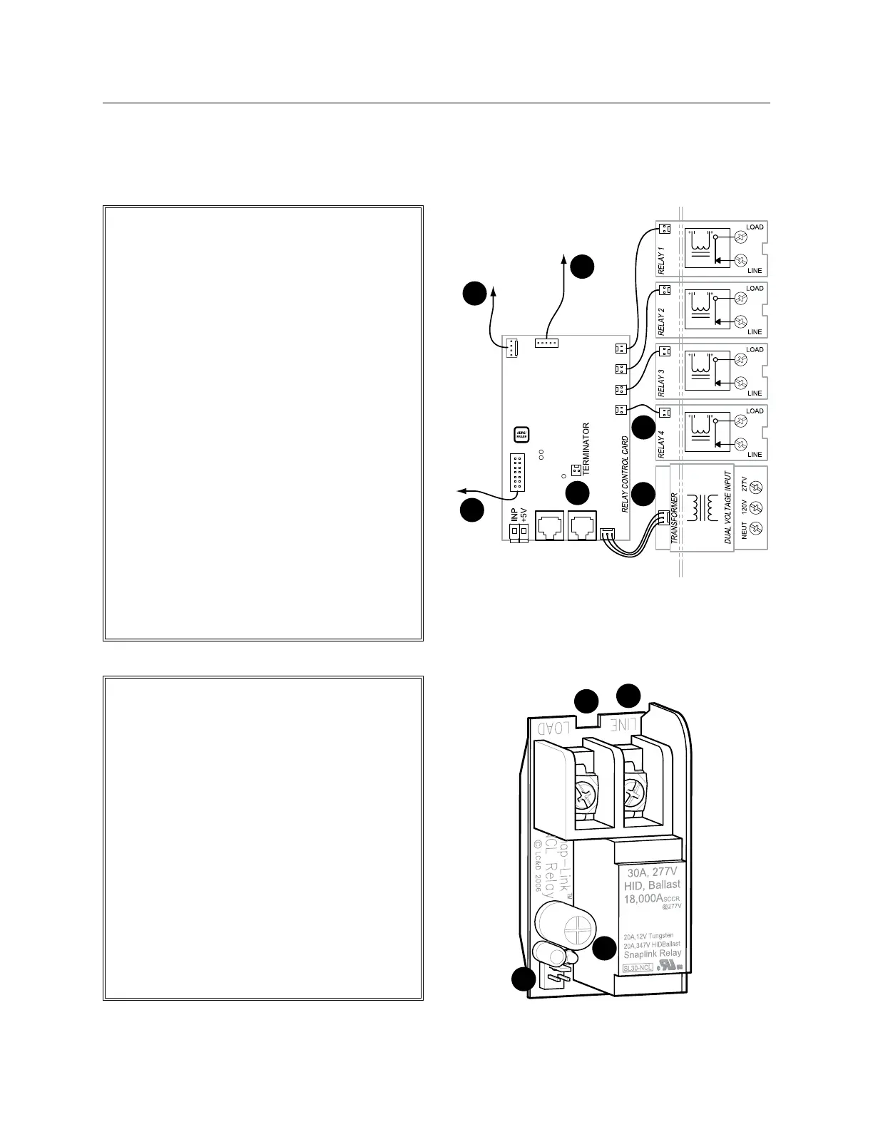
Low voltage connector.1.
Status indicator LED.2.
Quick removal slot.3.
High conductivity terminal block.4.
SnapLink
™
Latching Relay: Normally closed latch-
ing (NCL), UL listed for 30 amps lighting (ballast,
HID) at 277v, 20 amps at 347v and 20 amps
Tungsten at 120v, 18,000 amp SCCR at 277v,
rated 250,000 on/off cycles, 3 yr. warranty.
RELAY OvERvIEW
3#18 AWG. Supplies power from trans-1.
former to relay control card.
14 conductor ribbon cable: carries control 2.
signal between DTC and relay control card
(master panel only).
2 conductor ribbon cable: carries control 3.
signal from smacker strip to relays - one
per relay.
5 conductor ribbon cable: carries digital 4.
signal from relay control card to (optional)
digital input card.
4#22AWG carries RS-232 signal from 5.
(optional) modem to relay control card
(master panel only).
Terminator pins. Add terminator here if this 6.
is the first or last item on a bus (follow the
“System Start-Up & Cabling Guide”).
For more information about external hook-ups,
refer to GR 1404 LT Installation Guide.
BLUE BOX LT 1404/1408
INTERNAL SCHEMATIC
1
2
3
4
2
3
6
4
5
1
To optional
DI Card
To optional
Modem
master panels
only
To DTC
 Loading...