THE BLUE BOX LT OVERVIEW 9
LCDBBO03Sept08
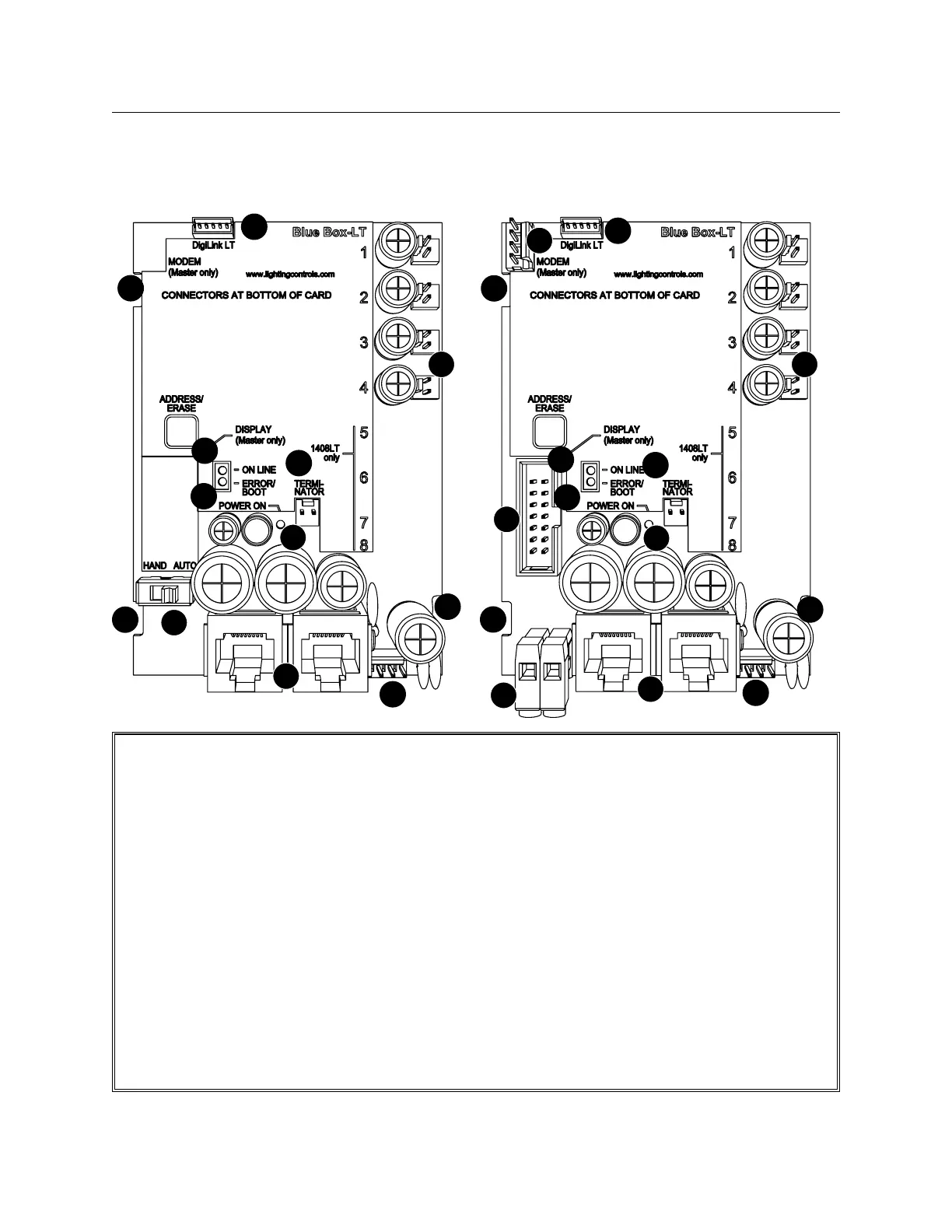
GR1404/08 SLAvE PANEL RELAY CONTROL CARD
1
2
4
10
11
7
8
9
7
7
12
13
GR1404/08 MASTER PANEL RELAY CONTROL CARD
3
5
6
7
7
2
4
1
10
11
8
9
7
13
Relay Drivers. Opto-isolated to prevent line volt-1.
age back-feed and to help prevent RF and EMF
noise interference. Relay drivers will close latching
relays upon loss of power to the Control Card.
RJ45 sockets for digital bus. Digital devices (relay 2.
panels, digital switches, etc) connect to this panel
using a bus (daisy-chain) topology.
Photocell port (master panel only). +V output 3.
with a photocell input. Photocells are polarized -
follow color code.
Power/data connector for DI Card.4.
Power/data connector for modem (master panel).5.
Power/data connector for DTC clock/display 6.
(master panel only).
Removal slots for control card. Used with a flat 7.
blade screw driver to remove the Control Card.
Terminator pins. Add terminator here if this is the 8.
first or last item on a bus (follow the “System
Start-Up & Cabling Guide”).
Online LED indicates the communications mi-9.
cro-processor is functioning, not that the panel
can see the digital bus.
Power ON LED indicates the control card is re-10.
ceiving power from the transformer and has suc-
cessfully converted it to DC.
Error/Boot LED. Flashes continuously if system 11.
failed to boot.
Hand/Auto Switch (slave panel only). In Auto 12.
mode, relays will react to schedules and switches.
In Hand mode, relays will remain closed.
Power input from transformer.13.
 Loading...