THE BLUE BOX LT MAKING UP CAT. 5 CABLE WITH RJ45 CONNECTORS 29
LCDBBMUCAT03Sept08
All Lighting Control & Design systems use Cat. 5 cable with
RJ45 connectors to network devices. While both our sys-
tem & Ethernet networks use Cat. 5 cabling, there are huge
differences between the two (Note: Cat. 6 is often substi-
tuted for Cat. 5. Our system accepts either type of cable.)
ETHERNET NETWORk
Typically Ethernet networks have multiple devices con-
nected to a central point, this design scheme is called a
star topology (Figure 1.1 illustrates a multi-level star topol-
ogy). In this example, the four workstations are connect-
ed directly to a switch/hub, which is connected to another
star to access either the file server, printer or router.
The hub/switch receives the data sent by the four work-
stations; upon receipt of the data, the hub/switch checks
the data for errors and re-transmits to another switch to
access the other devices on the network. The data travels
only one section of the cable before it gets cleaned up or
repeated and forwarded to another point. Thus any incon-
INTRODUCTION
sistent quality in the Cat. 5 cable or crimp will not severely
impact this network’s stability. It may slow the data trans-
mission on one leg of the network, but not as to affect the
other nodes on the network.
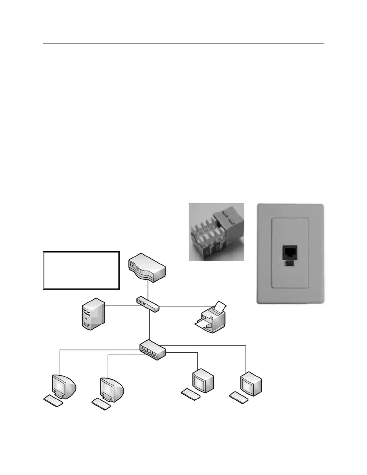
In an Ethernet network, one cable is connected to the
switch, workstation, printer, etc. and terminated at a jack
socket in the wall (Figure 1.2a and 1.2b). This socket has
insulation displacement connections, which do not require
crimping. The cable from the wall socket to the device is
typically a factory-manufactured cable. These cables use
flexible stranded wires and crimps made on pneumatic
crimping machines, which exert several hundred pounds
of pressure to ensure an excellent crimp.
Figure 1.1 - Typical Eth-
ernet Network Setup
Ethernet uses Cat. 5 cables,
each cable does not exceed
100 meters (330ft).
Router
File Server
Switch
Printer
Switch/Hub
Workstation 1 Workstation 2 Workstation 3 Workstation 4
Figure 1.2a: Insulation
Displacement Socket
Figure 1.2b
 Loading...