THE BLUE BOX
™
LT
SYSTEM START-UP & CABLING GUIdE
INSTRUCTIONS:
STEP 1:
Install all equipment and note down their serial numbers on
the
“System Device Schedule” in The Blue Box LT Master
Panel
......................(Refer to Installation Guides)
STEP 2:
Pull Cat. 5 cable in a daisy-chain between all digital devices.
Add “EZ” brand RJ45 connectors to cable ends and crimp
using the proper color code. Note:
Do not connect contact
switches or photocells until Step 5.
.............Pgs.96-97
STEP 3:
Test each cable with a LAN tester and once passed plug
each in. Do not power-up devices until Step 6! .....Pgs.97
STEP 4:
Verify proper connections and cabling using the Hardware
Activation Tests...................................Pg.98
STEP 5:
Make up low voltage cabling and connections for contact
closure devices or photocells. .... (See Installation Guides)
STEP 6:
Start-up and auto-address the digital bus. ......... Pg.99
Once the 6 steps are completed you can program sched-
ules, switches, and photocells. Need help? Call Tech Support:
(800) 345-4448.
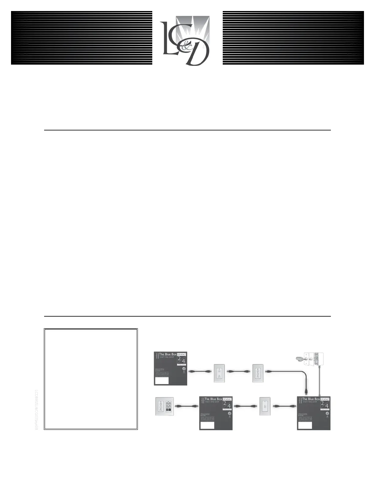
Chelsea Digital Switch
Slave Relay Panel
Outdoor Photocell
Master Relay Panel
Slave Relay Panel
®
Digital Network:
Locate multiple Blue Box LTs and
control stations where you need
them and then link them all with
Cat. 5 cable. One master panel
(with a Digital Time Clock) for 16
digital devices. Control stations
provide combined manual control
and after-hours override.
Note: The photocell is not on the
digital bus and should not be con-
nected until Step 5.
 Loading...