96 THE BLUE BOX LT SYSTEM START-UP & CABLING GUIDE
LOW vOLTAGE CABLING
Digital devices have two RJ45 connectors and are daisy-
chained using Cat. 5 (see cover). Non-digital devices (pho-
tosensors, toggle switches, etc.) are cabled per their instal-
lation guides (not daisy-chained).
!
Adhere to 568A or 568B standards for Cat. 5 cables.
Always use a dedicated pair for the center pins.
Refer to individual product installation guides for line-volt-
age cabling details and low voltage connection details Do
not “home run” digital switches back to a relay panel. No
spurs or T-Taps are allowed. Do not exceed 16 devices on
any system with a Blue Box LT Master.
ELIMINATE INTERFERENCE; ISOLATE CAT. 5
CABLES
…From Line Voltage Cable: Cat. 5 cable must be at least
12” from all line voltage conductors, except to cross or
make terminations.
Photosensor
Input
Relay
Relay Panel
Low Voltage Cable
Line Voltage Cable
Photosensor
Low voltage cabling must not be run in parallel with
line voltage cable, and must not share the same conduit,
whether digital cable (Cat. 5) or low voltage cable (3#18
from a photosensor).
…From Line Voltage Devices: Low voltage cabling must avoid
EMF or RF from ballasts, arc welders or other “noisy” loads.
EMF or RF interference can create an unstable bus.
Photosensor
12" or more
Photosensor
Input
Relay
Relay Panel
Line Voltage Cable
Low Voltage
Cable
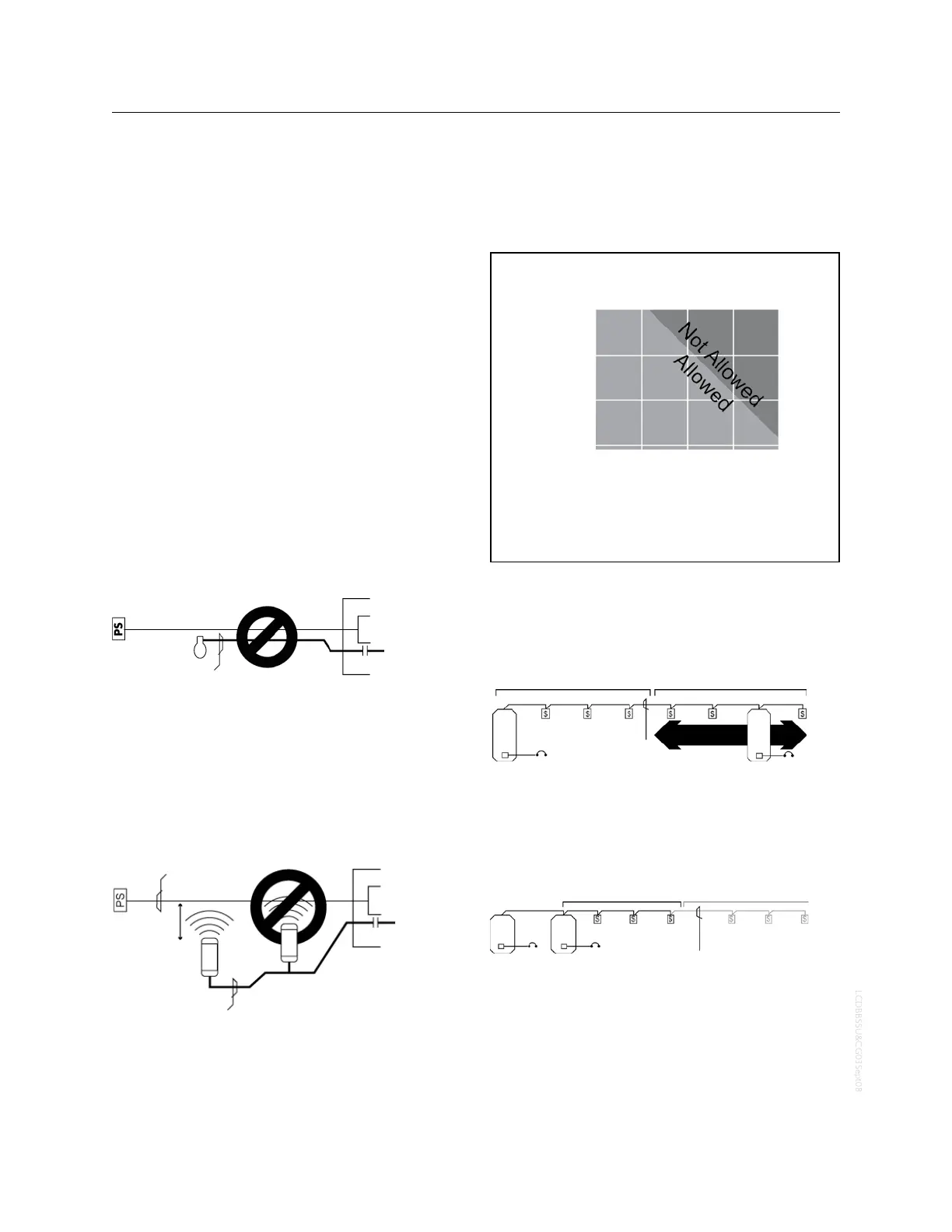
DON’T CAUSE vOLTAGE DROP!
There is a limit to how many switches and photocell cards
you can add in a row over long runs of Cat. 5 cabling.
Bus-Powered Devices Allowed
for Each Active Device
Number of Bus-Powered Devices
Total Feet of Cable from
One Active Device
1000 ft.
900 ft.
800 ft.
700 ft.
3
6
9
12
Active Device - Device with power supply (a transformer). It acts as a
source of electrical energy for the bus.
Bus-Powered Device - Any device that relies on the 12v supplied by the
bus for its power. Example: digital switches, and photosensor cards.
The more feet of Cat. 5 cable used, the fewer bus-pow-
ered devices before adding another active device.
Examples: Per the above chart, up to 3 bus-powered de-
vices may be powered across 1,000 feet of Cat. 5 cable.
Bus-Powered Devices
Cat. 5 Cable
Power
Power
Active Device
Active Device
Active Device Anywhere
in the 1000 ft. zone
The active device may be located anywhere within the
1,000 foot region.
Multiple active devices in the same location will not in-
crease the distance allowed.
1000 ft. Insufficient Power
Bus-Powered Devices
Bus-Powered Devices
Cat. 5 Cable
Power
Power
Active Devices
For the above, the correct solution is to connect the ac-
tive devices (relay panels) as the center of the network
and have two runs of cable. Call the Tech Support if cable
runs exceed 1000ft without active devices.
 Loading...