LCDBBAND04Sept08
THE BLUE BOX
™
LT
AddING A NEW dEVICE
INSTRUCTIONS:
STEP 1:
Install new devices and note down their serial numbers on
the
“System Device Schedule” in the Master Panel
(Refer to
Installation Guides)
STEP 2:
Remove terminators from both ends of the bus.
STEP 3:
Pull Cat. 5 cable in a daisy-chain to new devices. If convenient
new devices can be added to the middle of the existing bus.
(Never splice Cat. 5 cable!). Add “EZ“ brand RJ 45 connec-
tors to cable ends using the proper color code.
.
... Pg.41
STEP 4:
Test new cables with a LAN tester and once passed plug each
in. Do not power-up devices until Step 7........Pgs.41-42
STEP 5:
Verify proper connections and cabling for the entire bus using
the Hardware Activation Tests ......................Pg.42
STEP 6:
Make up low voltage cabling and connections for contact
closure devices and photocells. ... (See Installation Guides)
STEP 7:
Power-up and auto-address new devices.......... Pg.43
STEP 8:
Verify the system is operating without errors .....Pg.45-46
STEP 9:
Begin Programming..................(See O&M Manual)
Chelsea Digital Switch
Slave Relay Panel
Outdoor Photocell
Master Relay Panel
Slave Relay Panel
®
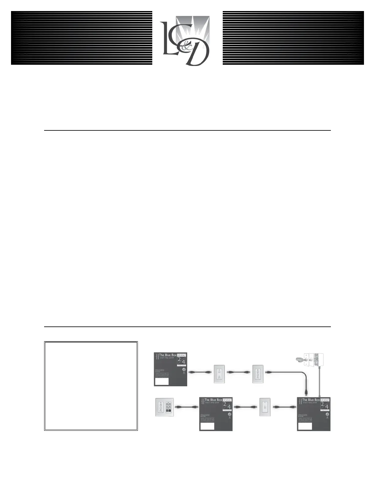
Digital Network:
Locate multiple Blue Box LTs and
control stations where you need
them and then link them all with
Cat. 5 cable. One master panel
(with a Digital Time Clock) for 16
digital devices. Control stations
provide combined manual control
and after-hours override.
Note: The photocell is not on the
digital bus and should not be con-
nected until Step 5.
 Loading...