THE BLUE BOX LT OVERVIEW 19
LCDBBO03Sept08
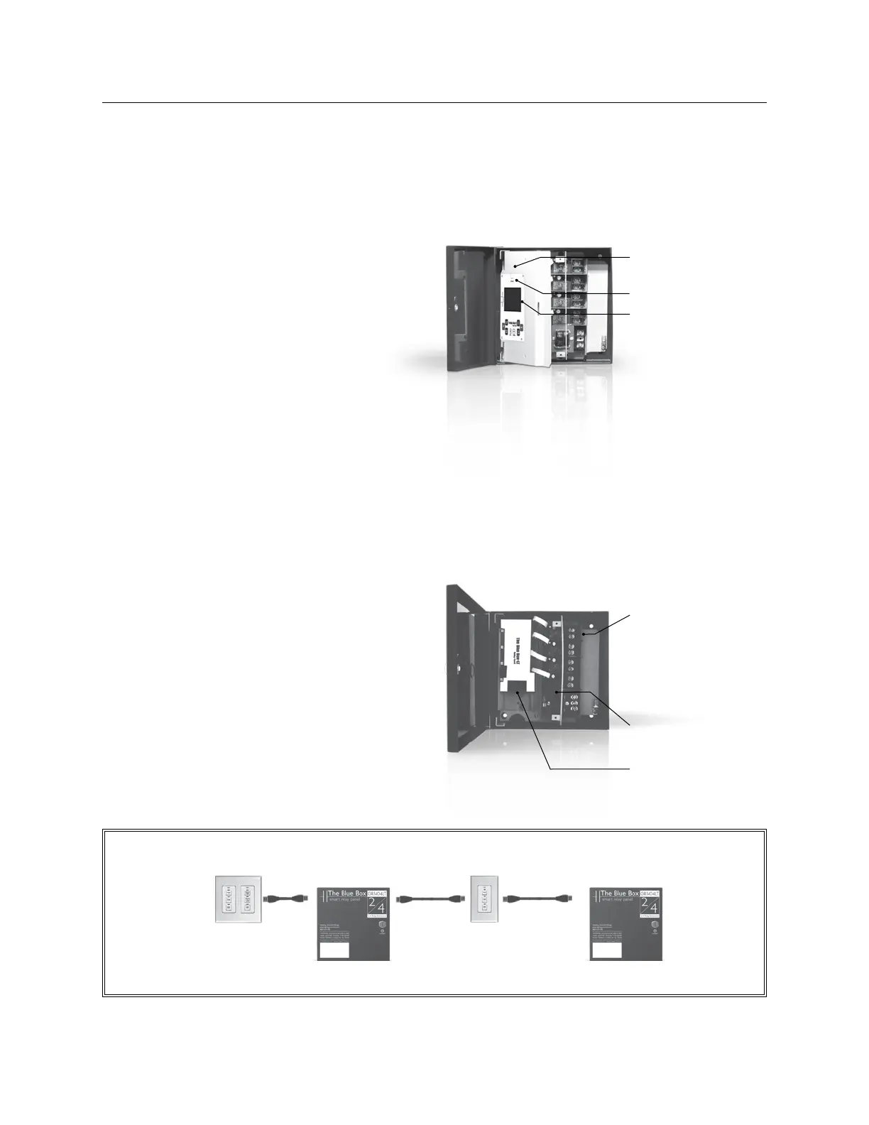
2 PANEL CONFIGURATIONS
Master Relay Panel
Modem for remote pro-
gramming
Optional Hand/Auto Switch
DTC clock/programmer
• 32 channel 365 day, 7
day astronomical clock
• Programming access for
time schedules, switches,
photocell etc.
• Large format screen
Slave Relay Panel
Lighting relays:
• 30A @ 277V Ballast
• 20A @ 120V Tungsten
• 20A @ 347V Ballast
• SCCR 18,000 Amps
Power supply:
• 120V/277V
RJ45s inputs for digital bus
MASTER RELAY PANEL
Each system needs one master panel equipped with: DTC
clock/programmer. Program schedules, switches and pho-
tocells for multiple panels.
365-day/7-day/astronomical 32 channel clock•
Plain English command prompts•
Non-volatile memory for all programming, 10 year •
battery back-up for time of day
Photocell Input: One photocell can control any relay in
any panel.
Optional modem and Digital Input Card (See pgs. 10-11,
“Accessories”).
Control up to 16 devices.
SLAvE RELAY PANEL
The slave panel is a fully programmable panel that net-
works to the DTC, modem, and photocell from the mas-
ter panel.
No DTC, photocell input, or modem is required in a slave
panel, as it uses the master panel.
Option: Digital Input Card allows dry-contact closure
switches to control any relay in any panel – wall switches,
momentary switches, occupant sensors or any other dry
contact switch
(See pgs. 10-11, “Accessories”).
Chelsea Digital SwitchChelsea Digital Switch
Master Relay Panel Slave Relay Panel

 Loading...