THE BLUE BOX LT OVERVIEW 17
LCDBBO03Sept08
STEP 1: MASTER PANEL
How many circuits (relays) do you need to control? (See
pgs. 6-7 for enclosure sizes).
Do you need a modem for remote dial-up programming?
(See pg. 10, “Modem”).
Do you need inputs for occupant sensors, or contact clo-
sure switches? (See pg. 10, “Digital Input Card”)
STEP 2: SLAvE PANELS
For each additional Blue Box
™
LT, how many circuits (re-
lays) do you need to control? (See pgs. 6-7).
For each additional Blue Box
™
LT Series, do you need in-
puts for occupant sensors, or contact closure switches?
(See pg. 10, “Digital Input Card”)
Up to 16 panels and switches may be controlled on the bus.
STEP 3: SWITCHES, OUTDOOR PHOTOCELLS &
ACCESSORIES
How many override switches do you need?
How many buttons on each switch? (1 to 6 buttons cost
the same).
Will you need a photocell to supplement the DTC astro-
nomical clock? (See pg. 10, “Digital Photocell”).
Add other accessories as shown on pages 10-11.
Control up to 16 devices.
Every system must have a Master Panel which contains
the clock and photocell inputs and connections for the
optional modem.
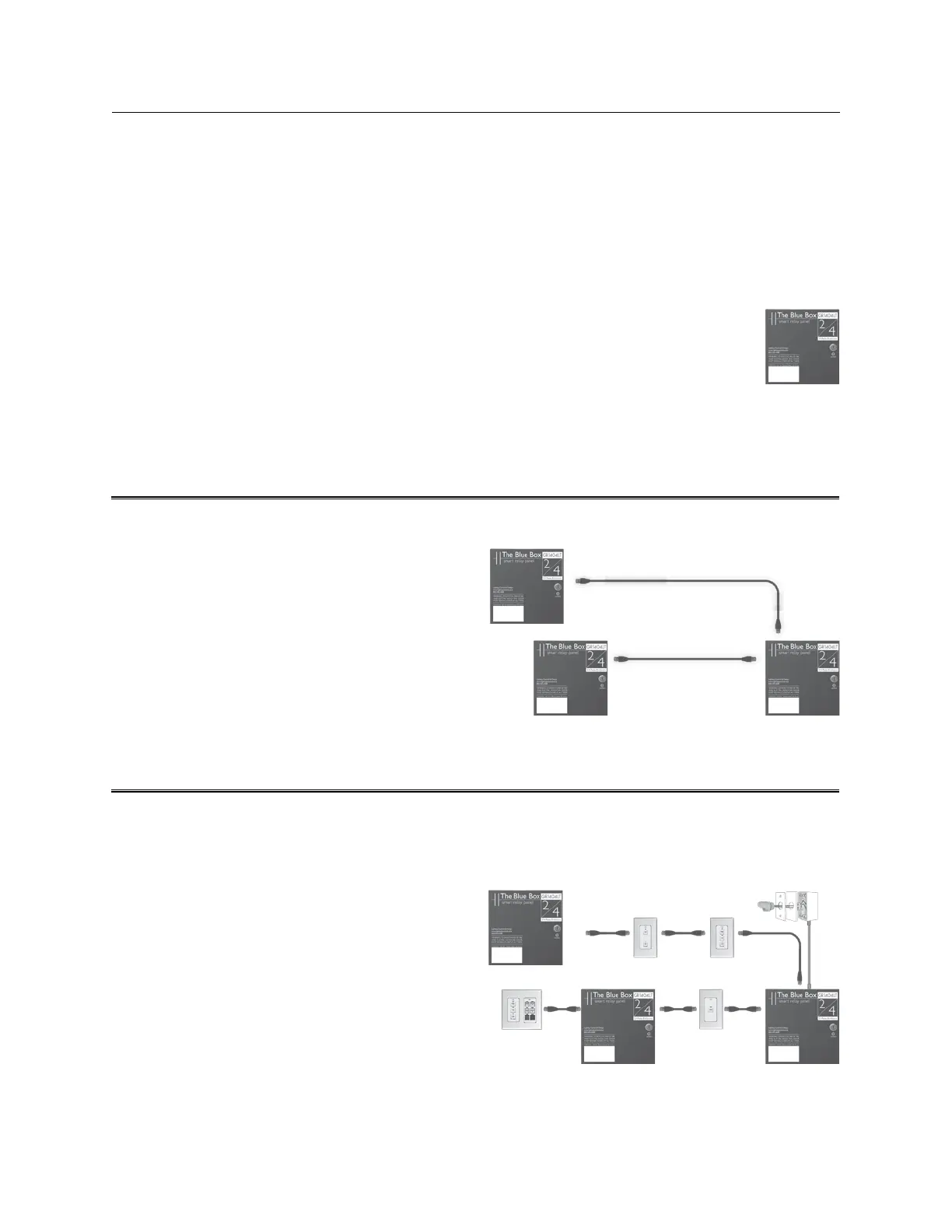
BUILD YOUR SYSTEM IN 3 STEPS
Master Relay Panel
Each system needs one master panel. Use one Blue Box
™
for each electric room you are controlling lighting circuits in.
Slave Relay Panel
Slave Relay Panel
Outdoor Photocell
Chelsea
Digital Switch
Master
Relay Panel
Slave Relay Panel
Slave Relay Panel
Master Relay Panel
 Loading...