8 THE BLUE BOX LT OVERVIEW
LCDBBO03Sept08
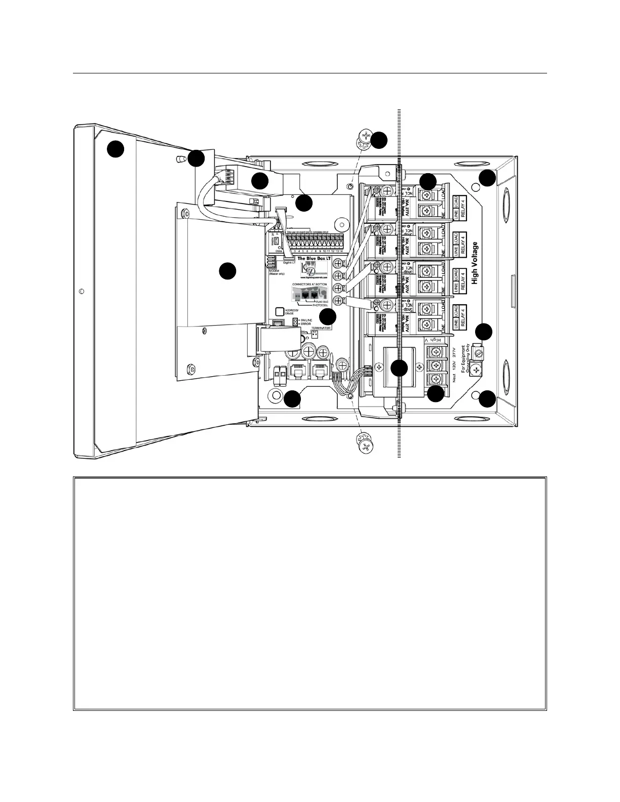
Screw fastener secures hinged Control Panel 1.
Door (Master only).
White door provides barrier between human 2.
interface and line voltage connections beneath
(Master only).
Optional Modem. Free factory dial-up programming.3.
Optional DI contact closure interface card.4.
Ø1/4" mounting holes at 4 places.5.
Optional: Unfasten two screws to remove chassis 6.
assembly from enclosure providing full access to
mounting holes if required.
SnapLink7.
™
relays, Normally-Closed (NC). Status
LED is ON when relay is OFF.
DTC Clock / Display & Programming Interface: 8.
32-channel, 365-day astronomical clock with
Scroll and Tab to access control features for en-
tire system (Master only).
Voltage barrier separates line voltage (class 1) & 9.
low (class 2) connections.
Dual Voltage Power Supply Input: Blue Box LT10.
™
operates on either 120V or 277V.
Ground Lug for equipment grounding.11.
Relay Control Card provides interface between 12.
control network and relays. The Relay Control
Card in the Master panel also holds time sched-
ules and system mapping.
GR1404/08 LT (WHITE DOOR OPEN)
1
3
2
4
10
11
5
6
7
8
low voltage only line voltage only
9
55
12
 Loading...