124 THE BLUE BOX LT PCO INSTALLATION GUIDE
LCDBBPCOIG03Sept08
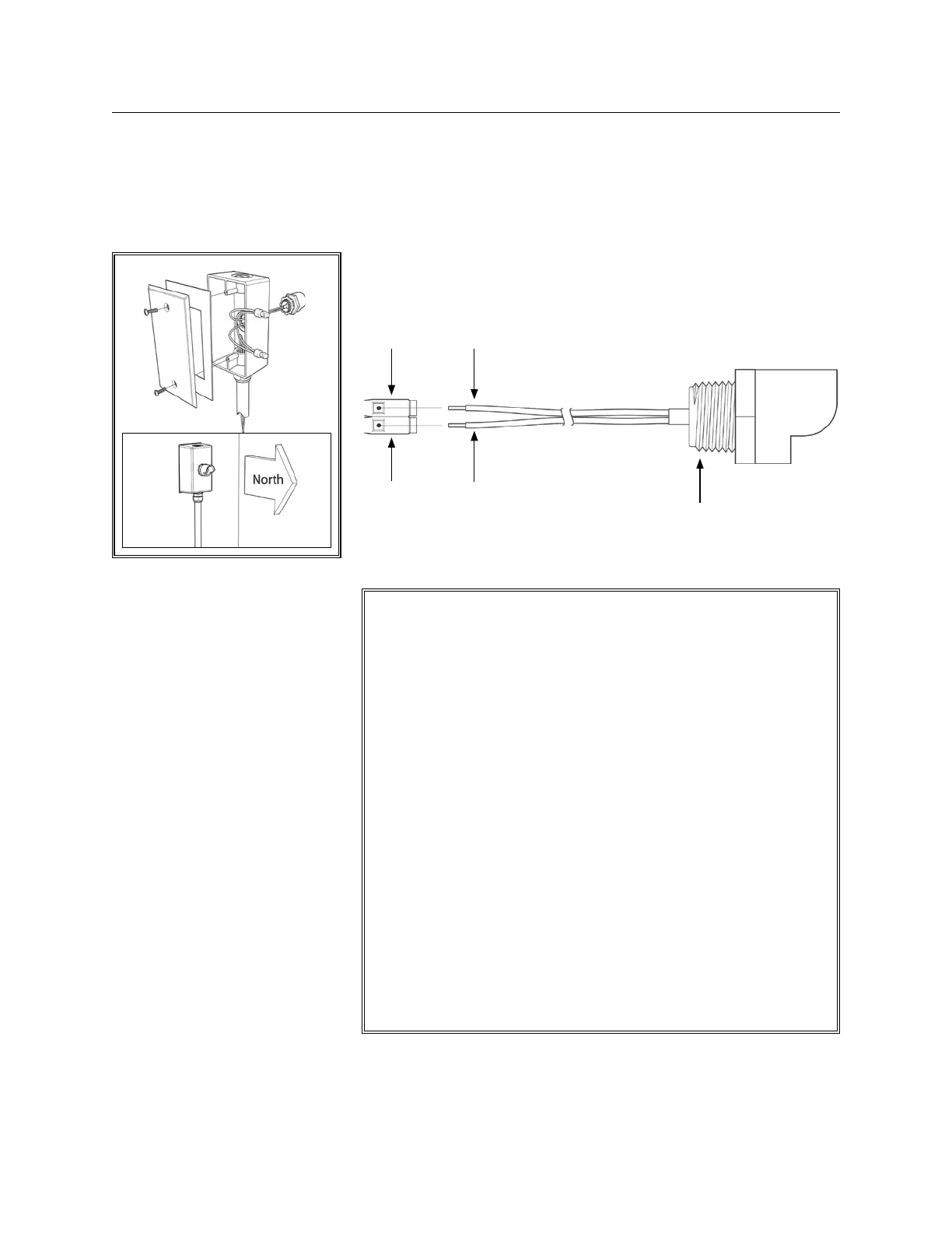
ROOF-MOUNTING THE PCO
Roof mount the PCO “hood up” 1.
with an as unobstructed view of
the north sky as possible. Avoid
aiming at any surfaces that might
reflect sunlight directly into the
PCO lens.
CONNECTION
Connect the PCO to the photo-2.
cell inputs of a master Blue Box LT,
a PCC1 or PCC3 photocell card
with 2#18, up to 300 feet away.
COMMISSIONING
Once the system has been pow-3.
ered up per the steps of the “Sys-
tem Start-Up & Cabling Guide”,
complete the following test to ver-
ify the photocell is connected and
aimed correctly — facing North.
Follow the correct commissioning
steps in the “Commissioning Pro-
cedures”.
INSTALLATION INSTRUCTIONS
Figue A:
Red conductor to 8v (common)
Blue conductor to “Input”
8v Red conductor
Input
Blue conductor
Read the Light Level from the 1.
photocell to ensure placement
and functionality.
When connected to a Blue
Box LT, navigate to :
MAIN MENU > USER MENU
> REVIEW SCHEDULE >
PCELL ON
When connected to a PCC
Card, n
avigate to:
MAIN MENU > USER MENU
> PROGRAM SWITCH >
PHOTOCELL (1 OR 3) >
TRIGGER (1-10) > ON
MODE/OFFMODE
If the display reads in the range 2.
of 0 – 1020, this test is a pass,
and programming can be
started.
If display reads “1020”: 3.
Cover PCO lens and check
readings. If readings drop close
to “0”, adjust the aim of the
photocell to avoid direct or
reflected sunlight. If display still
reads “1020” , check for re-
versed connection (see Figure
A above).
If reading is stuck at “0”, ensure 4.
photocell is securely connect-
ed. If reading does not change,
contact LC&D Tech Support.
PCO has a 1/2 threaded
nipple, with a locking ring
(if needed).
COMMISSIONING PROCEDURES
 Loading...