LCDBBPRIG03Sept08
48 THE BLUE BOX LT PARTS REPLACEMENT & INSTALLATION GUIDE
LC&D recommends that any suspect circuit be fault-
checked prior to re-energizing.
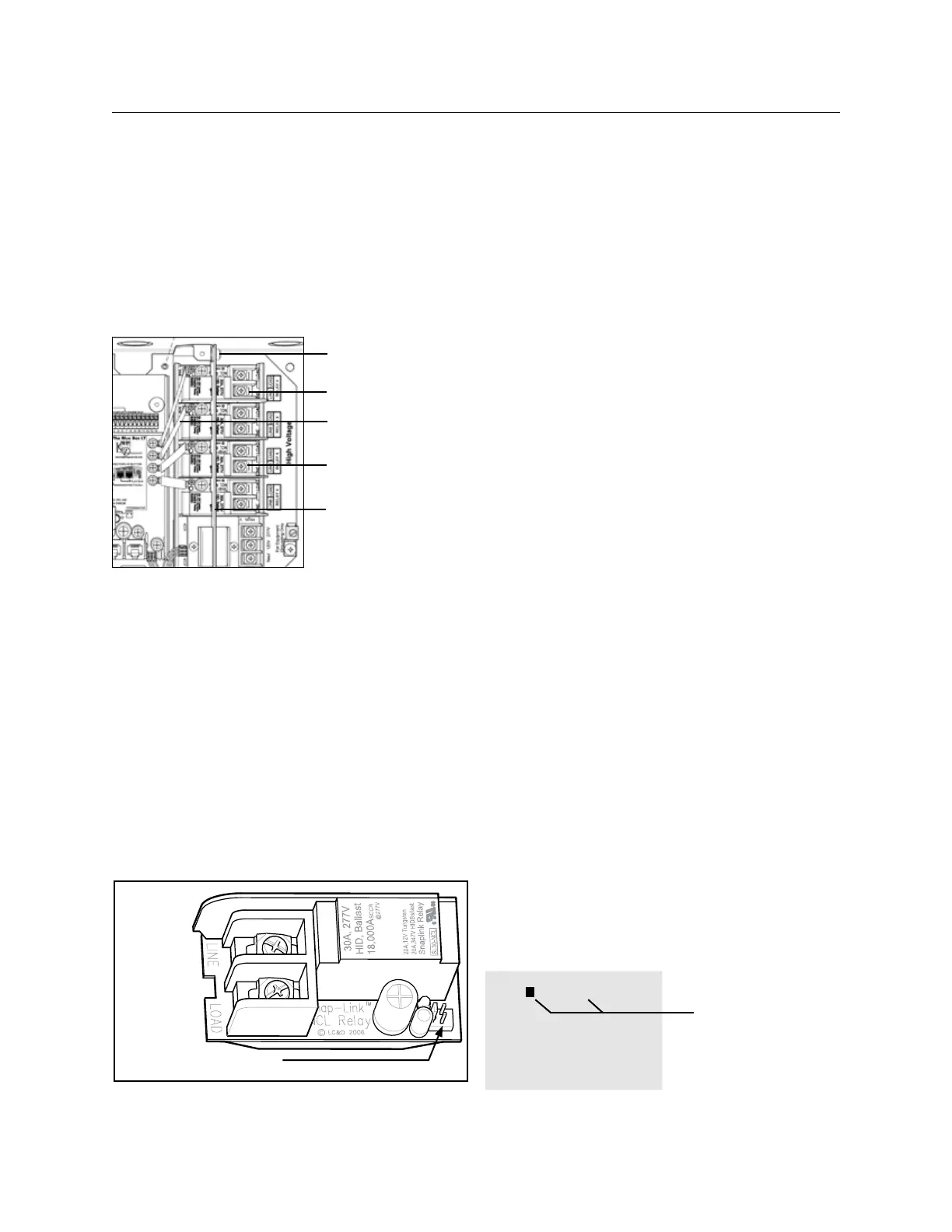
RELAY REPLACEMENT AND INSTALLATION
Screw/ Lockwasher
fasteners
Relays
Low Voltage jumper
connector
Line/Load Connection
lugs
line/low voltage
barrier
To remove a defective relay:
Switch off all breakers feeding relays and the 1.
transformer in the Blue Box LT.
For master panels: Unscrew and open the hinged 2.
display-panel door to expose the high-volatge section.
Remove the screw and lockwasher fasteners that 3.
hold the line/low voltage barrier over the relays.
Pull off the low voltage jumper that connects the relay to 4.
the control card (LT 4 & 8) or the smacker strip (LT 16).
Loosen the LINE and LOAD connection lugs on 5.
the relay and remove the conductors. [Note: For
safety reasons, use a wire nut to tie the two wires
together]
Line Lug
Removal Slot
Load Log
Low voltage connector pins
Pry the relay out of the plastic track by applying a 6.
flat-blade screw driver to the slot located at the
relay card’s edge near the line and load lugs.
To replace a defective relay
Push the replacement relay back into the track 7.
until it “snaps” securely in place – use a flat-blade
screw driver to snap in one or both ends.
Reconnect the low voltage jumper between the 8.
relay and the relay driver pins on the control card
(LT4 and LT8) or the smacker strip (LT16).
Re-install the line/low voltage barrier and the screw 9.
and lockwasher fasteners. If necessary, break out
the “break-away“ tab(s) (one for each new relay)
on the voltage barrier for the replacement relay(s).
Reconnect Line and Load conductors to the 10.
connection lugs.
For master panels: Close and screw down the 11.
hinged display-panel door.
After the defective part replacement installation 12.
is complete, return the part using the prepaid
USP return label and envelope to LC&D.
[Note: If the defective part is not returned within a
30-day period, your account will be automatically billed
for the part. ]
To exercise and test the replacement relay:
Switch the breakers powering all the relays and 13.
the transformer back ON
Navigate on the DTC to USER MENU > 14.
MANUAL OVERRIDE and TAB or SCROLL to
the correct LCP and Load (relay) and ENTER to
exercise the relay by switching it on and off 3 or 4
times. If possible, listen to hear the relay contacts
clicking as they open and close.
MANUAL CONTROL AU
LCP-1 LOAD-1
1- 3■ 5■ 7■ 9- 11- 13- 15-
2- 4- 6- 8■ 10- 12- 14- 16-
SCROLL to select LCP
TAB to LOAD
SCROLL to select
LOAD
ENTER to toggle
status
 Loading...