8
lci1.com 574-537-8900 Rev: 03.02.21
Ground Control
®
TT
Leveling OneControl
®
Touch Panel (3K-5K)
Installation and Owner’s Manual
(For Aftermarket Applications)
CCD-0002700
7. Repeat steps 1-6 on the opposite side of the frame.
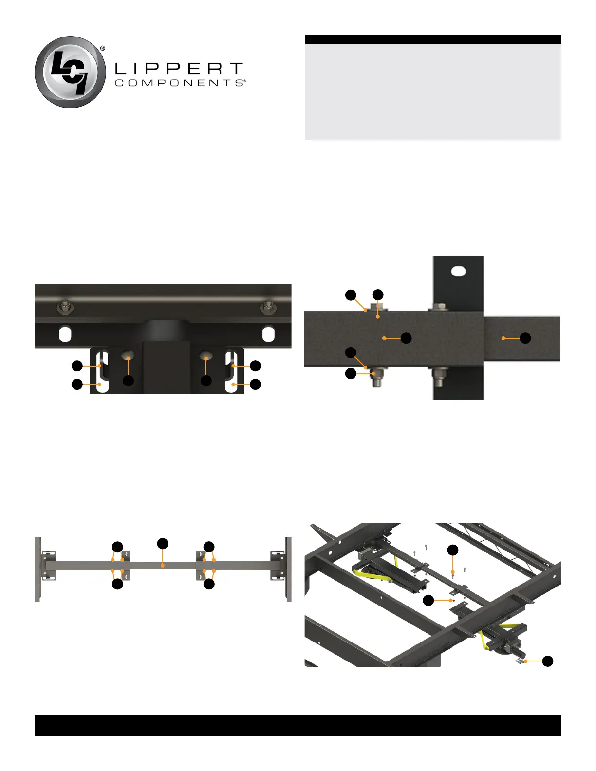
8. Align the tabs provided on the I-beam mounting bracket
(Fig.5A) with the slotted holes on the spacer bracket
(Fig.5B). Fasten the I-beam mounting bracket to the spacer
bracket with 5/16” carriage bolts (Fig.5C). Secure the carriage
bolts with 5/16” ange nuts. Torque nuts to 13 ft-lbs.
NOTE: The
5/1 6” carriage bolts (Fig.5C) will need to be fed
downward through the square opening.
9. Repeat step 8 on the opposite side of the frame
10. Insert the center tube (Fig.6A) into one of the spacer
brackets and slide until clear to insert into the spacer
bracket on the opposite side. Make sure that the center
hole or mark is facing downward on the center tube. Use
the hole to center the tube between both ends of the
I-beam mounting brackets.
NOTE: If there is no mark or hole for the center location on
the center tube, measure and mark the location.
Fig.5
Fig.6
B
A
C C
A
B
A
11. Use the eight pre-drilled holes (Fig.6B) on the spacer
brackets to mark holes on the center tube.
12. Drill the eight marked holes on the center tube with a
3/8” drill bit.
NOTE: Remove the center tube from the spacer brackets
before drilling, if desired.
B
B
B B
13. Insert two
3/8” hex cap screw bolts (Fig.7A) with 3/8” at
washer (Fig.7B) through the spacer bracket (Fig.7C) and
center tube (Fig.7D). Secure bolts with 3/8” at washers
(Fig.7B) and 3/8” ange nuts (Fig.7E). Torque nuts to 23 ft-lbs.
14. Do step 13 for the opposite side spacer bracket and
center tube.
A
B
B
C D
E
Fig.7
15. Align the C-Jack mounting holes with the holes on the
I-beam mounting bracket across the frame roadside to
curbside (Fig.8).
NOTE: Use the optional aid of a hydraulic floor jack to
assist in holding the C-Jack in place or manually open the
C-Jack so that the footpad is touching the ground. See the
“Troubleshooting” section “Manual Override” to fully extend
the C-Jack.
Fig.8
A
B
C