12
lci1.com 574-537-8900 Rev: 03.02.21
Ground Control
®
TT
Leveling OneControl
®
Touch Panel (3K-5K)
Installation and Owner’s Manual
(For Aftermarket Applications)
CCD-0002700
Determining the Mounting
Position and Installing
Leveling Sensors
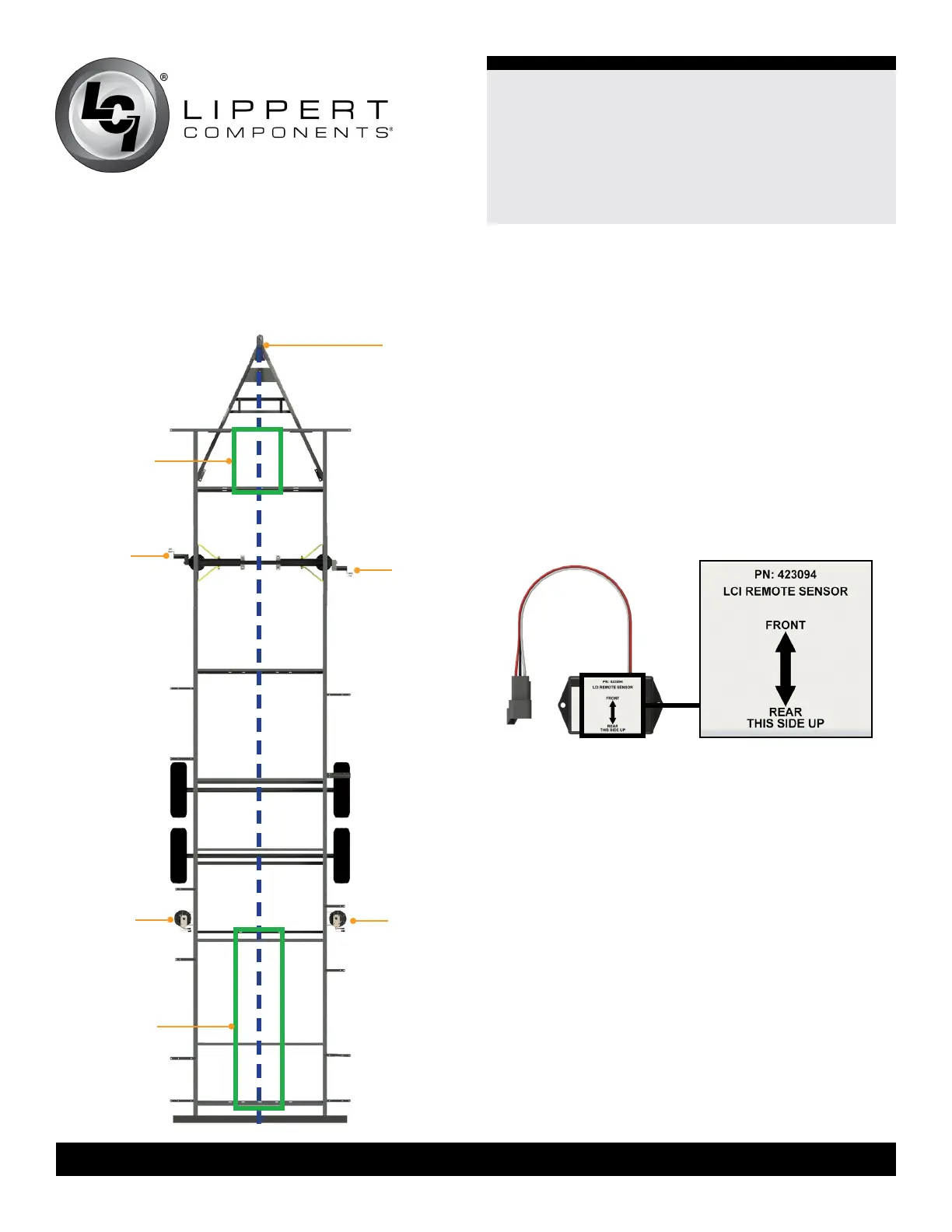
Fig.18
Installing Leveling Sensors
The leveling sensors have a limited mounting area for
proper performance. The front sensor must be within
36” from the front of the frame as signified by section A
in (Fig.18). Make sure the front sensor is mounted in line or
in front of the front leveling jacks. The rear sensor must be
in line with or behind the rear leveling jacks, as signified
by section B in (Fig.18). Both the front sensor and the rear
sensor must also be mounted in line with the center of the
frame, as signified by the dotted blue line in (Fig.18).
The Leveling Sensors (Fig.19) must be oriented on the
crossmembers with the arrows on the top of the sensor
pointing in the correct direction (Fig.19). See (Fig.18),
sections A and B, for location clarification.
front
left jack
front
right jack
roadside curbside
section A
power
tongue jack
front of
trailer
rear of
trailer
section B
rear
left jack
rear
right jack
Fig.19
NOTE: The following process will be repeated for both
sensor installations.
NOTE: If the frame is Ground Control Travel Trailer ready,
it may be possible that the Leveling Sensor Mounting Plate
may have already been pre-installed onto the frame.