14
lci1.com 574-537-8900 Rev: 03.02.21
Ground Control
®
TT
Leveling OneControl
®
Touch Panel (3K-5K)
Installation and Owner’s Manual
(For Aftermarket Applications)
CCD-0002700
Controller Installation
NOTE: Prior to starting this portion of the installation,
double check that all of the harnesses are properly and
securely connected to the leveling jacks, Power Tongue
Jack and leveling sensors.
NOTE: The compartment where the controller will be
installed must be protected from the elements and the
controller must be installed in compliance with RVIA Gas
Codes, as the controller connections are not spark-proof.
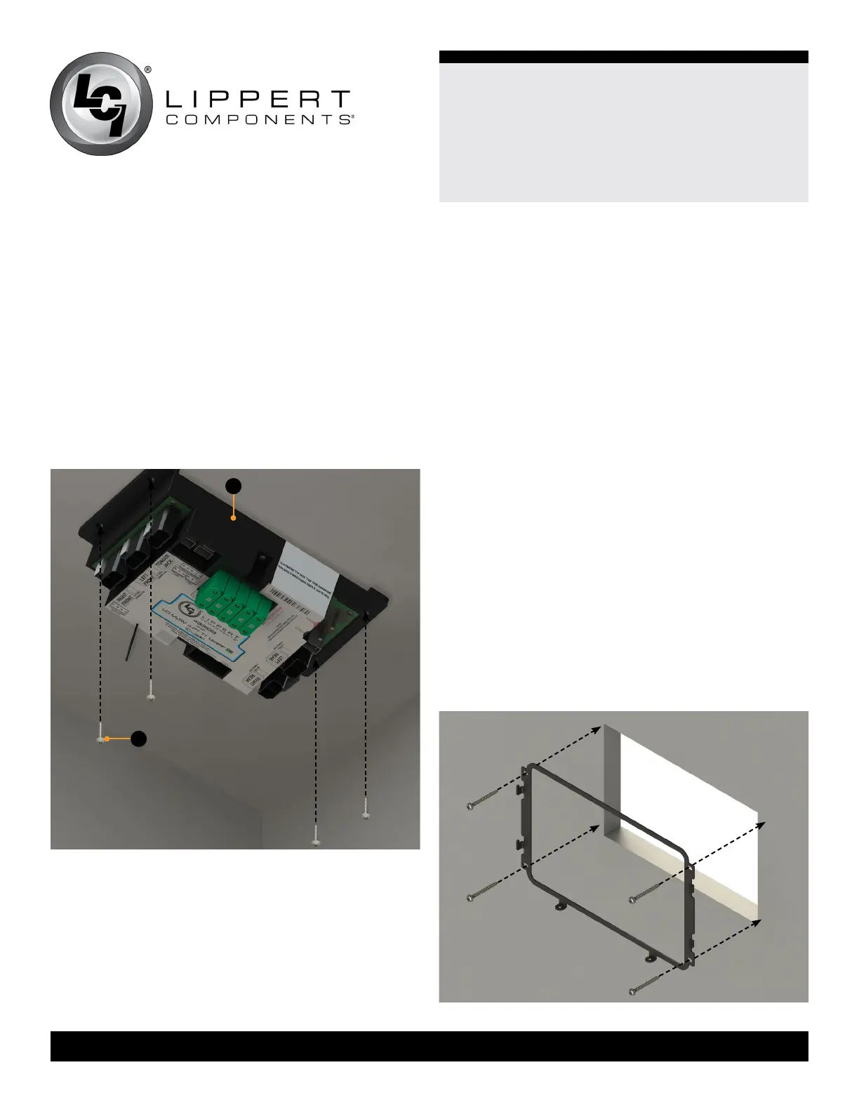
1. Using four #8 x 1” wood screws (Fig.24B), attach the
controller (Fig.24A) to the compartment wall or ceiling.
Fig.24
2. Attach the power and ground harnesses to the
corresponding posts on the controller with the provided
keps nuts and then connect the harnesses to the correct
posts on the trailer battery.
3. Connect all jack harnesses to the appropriate
connectors on the controller. Insert one terminating resister
into the open CAN port on the controller. See the Wiring
Diagram section.
OneControl Touch Panel/Pad
Installation
OneControl Touch Panel
1. Determine where to mount the OneControl Touch Panel.
The touch panel can be mounted anywhere inside the
trailer or trailer compartment. The mounting location must
be watertight. The typical location for the touch panel is
near the entry door.
2. Dry t mounting bracket where controller will be located.
3. Cut a hole in the wall of the compartment using the
inside opening of the bracket as a guide. Use the bracket
to trace where the cut-out should be located. The top and
bottom horizontal cuts should be parallel to the oor of the
trailer or trailer compartment.
4. Secure the mounting bracket with the four provided ¼”
Phillips pan head sheet metal screws (Fig.25).
5. Feed the touch panel harness (signal to the touch panel)
and canbus power connector (power to the touch panel)
through the bracket and run to the compartment where
the controller is mounted. Plug the harness and canbus
power connector into the appropriate connectors on the
controller. Insert one terminating resister at the back of
the OneControl Touch Panel in the canbus port. See the
Wiring Diagram section.
Fig.25
B
A