7
lci1.com 574-537-8900 Rev: 03.02.21
Ground Control
®
TT
Leveling OneControl
®
Touch Panel (3K-5K)
Installation and Owner’s Manual
(For Aftermarket Applications)
CCD-0002700
Mounting Brackets and
Jack Installation
THE TRAILER MUST BE SUPPORTED PER
MANUFACTURER RECOMMENDATIONS BEFORE
WORKING UNDERNEATH. FAILURE TO DO SO MAY
RESULT IN DEATH OR SERIOUS PERSONAL INJURY.
Front Bolt On Spacer Kit and C-Jack Installation
This bracing system is to be mounted across the frame
(roadside-to-curbside) and jacks are to be installed
roadside-to-curbside as well.
Make sure that all wires and hoses are clear from the
path going from the curbside I-beam mounting bracket
to the roadside I-beam mounting bracket before starting
the installation.
1. Measure the I-beam mounting bracket and make a mark
at the center. This will be the center of the C-Jack footpad.
2. Measure from the front of the frame and make a mark
at 60” (Fig.1). This will be the maximum allowable distance
for the location of the center of the C-Jack footpad. The
nal location should be as close to the draw bar (Fig.1) as
possible, staying within the approach angle (Fig.1). Make
sure the bracket lip is ush with the outside lip of the
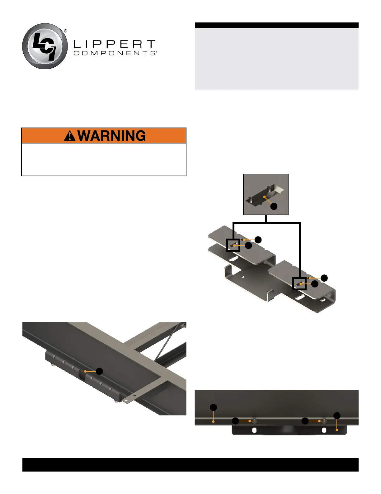
I-beam (Fig.2A).
A
Fig.2
3. Use clamps to hold the I-beam mounting bracket to
the frame rail.
4. Mark the four holes on the lip of the I-beam frame
with the spaces provided on the bracket (Fig.3A). Use
the notches on the I-beam mounting bracket to nd the
center point.
NOTE: The center point is dependent on the width of the
frame. The hole (Fig.3B) needs to be drilled between the
two notches.
Fig.3
A
A
A
A
5. Drill a hole into the frame as marked in step 4 for all
carriage bolts.
6. Fasten the I-beam mounting bracket (Fig.4C) to the
I-beam frame (Fig.4A) with four
5/1 6” carriage bolts
(Fig.4B). Secure the carriage bolts with 5/16” ange nuts.
Torque nuts to 13 ft-lbs.
NOTE: The 5/ 16” carriage bolts will need to be fed upward
through the C-channel of the I-beam mounting bracket.
B
Fig.4
A
B B
C