03-09-05 9
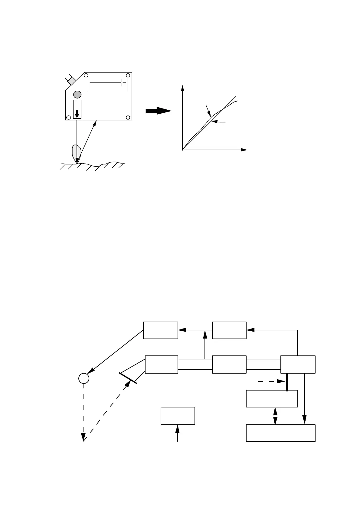
Linearization
SELCOM
SLS5000
Scattered
light reflection
A small portion of
the scattered light
Detector output
Desired
function
Non-linearized
function
The function between the raw output from the detector and the actual distance
between the SLS sensor and the measured object is non-linear. This non-linearity
is mainly due to the geometry of this type of measurements and to the analog
portion of the data processing. Therefore each sensor is factory calibrated to
compensate for any non-linearity or other built-in error. Using a moving target
and a reference scale a translation table is constructed and stored in non-volatile
memory inside the sensor.
Figure 6: Illustration of linearization
3 Technical data
Block diagram
Principal diagram:
DSPPreamplifierx1
x2
A/D-conv.
x1+x2
x1-x2
Laser
driver
Control
logic
Host processor
Internal data bus
Interface
Power
regulator
+ 24 VDC
Laser
diode
PSD
Figure 7: Principal diagram