03-09-05 26
+ 5V
Valid out
100 ohm
V+
SLS
connector
pin 12
pin 8
LOW = Invalid
HIGH = Valid
I = max 50 mA
4.7 k ohm
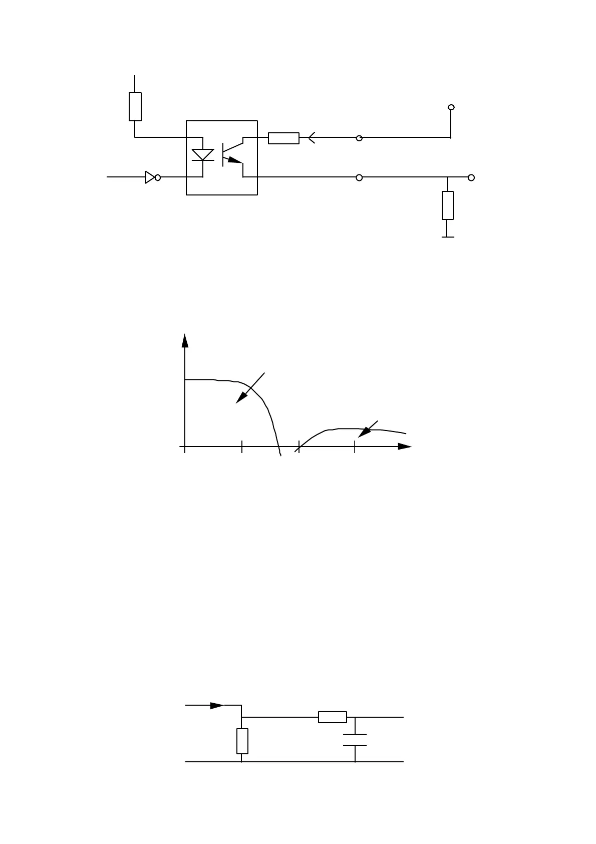
Figure 15: Example of connection (current source):
Cable crosstalk.
Due to cable crosstalk the spectral characteristics of the analog current output, as
measured over a 100 Ohm resistor, may have the following principal appearance:
1 10 100 kHz
SLS5000 signal spectrum
HF-noise spectrum
Figure 16: Illustration of spectrum
The analog output of the SLS sensor mainly finds its use in low bandwidth,
industrial measurement and control applications. The signal conversion equipment
in such applications is normally band limited to low frequencies making the
system insensitive or high frequency noise.
For some wide band applications like vibration analysis or when the signal is to be
manually studied with an oscilloscope, the high frequency noise may be a
problem. In these cases an anti-aliasing filter may be added between the load
resistor and the registration equipment.
A simple but in most cases sufficient filter is shown below. The components as
chosen will give an upper frequency limitation of 1.6 kHz. It is important that the
filter and the registration equipment is connected with as short cabling as possible
to avoid additional noise pick-up.
SLS5000
I (output)
Load
resistor
10 k ohm
10 nF
pin 13
pin 11
connector
Registration
equipment