03-09-05 35
Unstable thickness reading
1 In the case of a dual sensor system, the sensors will receive not only
reflected light but also the transmitted light from ”the opposite” SLS
sensor. Since they are working at nearly the same frequency, they will
interfere with each other. The output from the system will contain a low
frequency component (~1 Hz) even if the set up is in steady state. This is
an important phenomenon that has to be considered in all dual
applications. Note that special designed SLS sensors can be ordered to
avoid this phenomenon.
Advise
2 Single sensor thickness measurement using a mechanical reference.
Offset compensation for penetration can be useful if the material is
homogeneous.
3 Dual sensor thickness measurement on semitransparent materials.
Use SLS sensors designed for semitransparent materials.
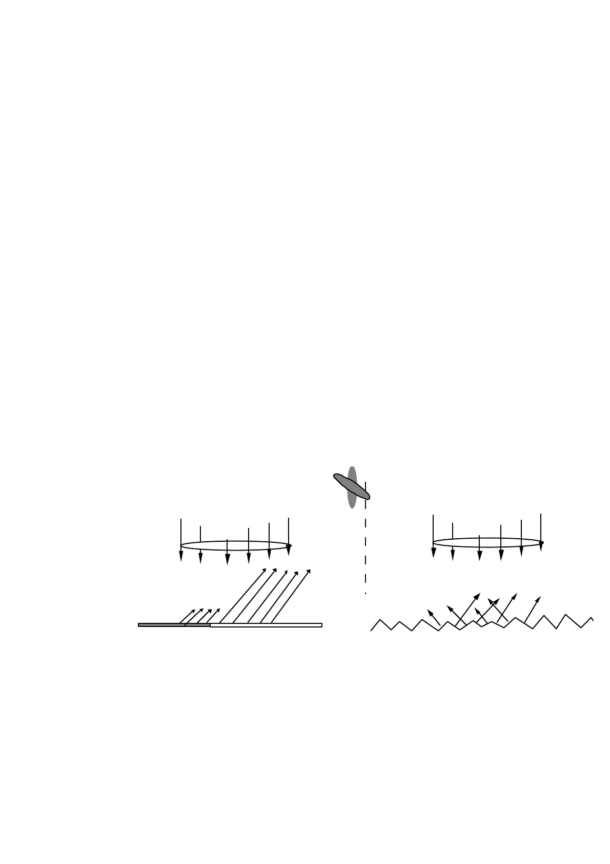
Surface texture. Static texture error
A basic statement to take care of is that the light spot produced on the target
covers a certain area and the SLS sensor will respond to the center of gravity of
the image of that spot on the detector. If the spot covers an area that gives an
irregular amount of scattered light in the direction of the receiving optics, the SLS
sensor reads a position of the surface below or above the true surface.
White surface
Black surface
Rolled steel
Receiving
lense
Laser
beam
Laser
beam
Figure 28: Reflection depending on target material
The change in the position output depends on the orientation of the sensor. The
magnitude and the duration in length depend on the size of the laser spot. As a
general rule the spot must be as small as possible. An example of output from the
SLS sensor is shown in the figure below.
Note that if the SLS sensor is rotated 90 degrees to the orientation indicated, no
error spikes occurs.