03-09-05 30
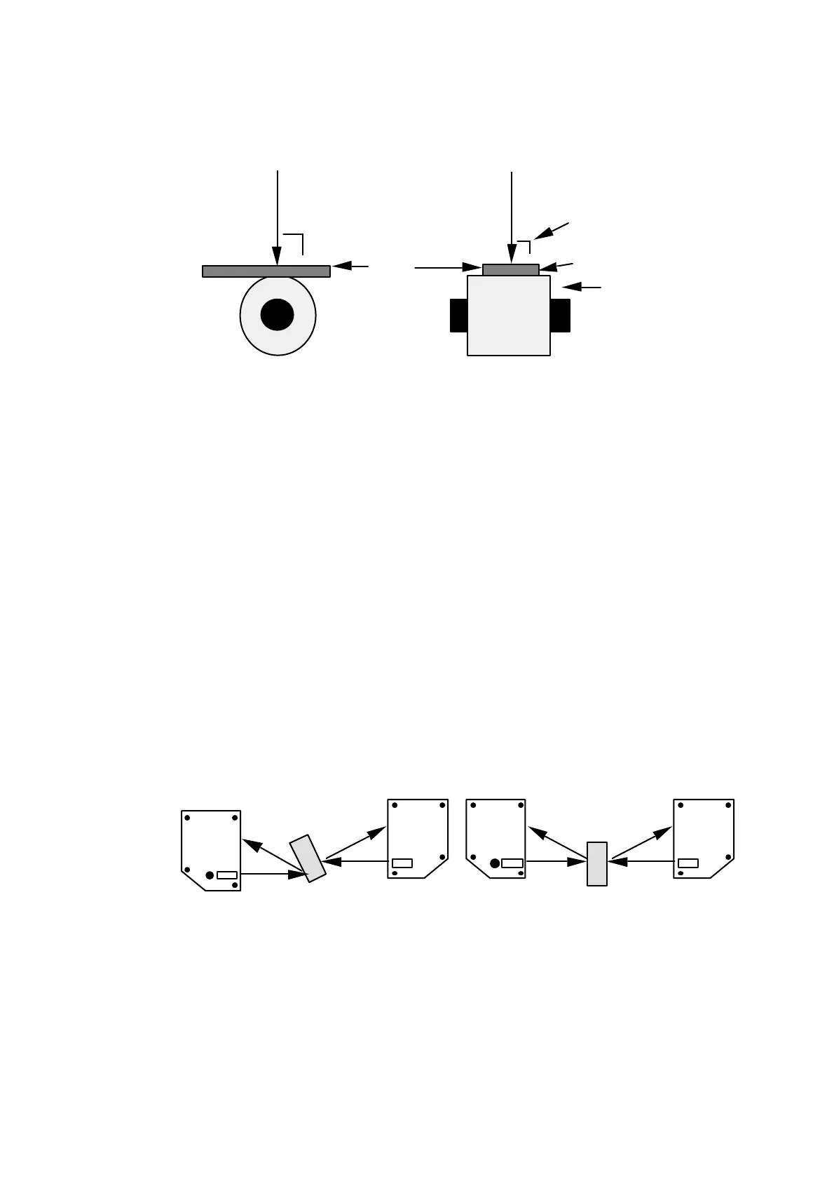
For a single SLS sensor system
The distance between the SLS sensor and the reference plane must not be
changed.
2
3
4
Target
Reference
roller
Reference
roller
11
Figure 20: Measurement against the reference plane
1. Laser beam
2. If the incoming laser beam is not perpendicular to the measured surface,
compensation for the angle may be necessary.
3. Good contact between the reference surface and the measured material is
important.
4. Eccentricity of a reference roll may cause variation in the thickness value.
Keeping track of the roll while performing multiple calibrations may solve
this problem.
For a dual SLS sensor system
The distance between the two SLS sensors must not be changed, between
calibration and measurement.
The accuracy of a dual SLS sensor system for thickness measurement is highly
dependent on laser beam adjustment of the two sensors. It is necessary to have the
two laser beams concentric through the entire measurement range. In the left
figure below, the thickness will decrease when the measured object is tilted as in
the figure and increase (more than correct) when tilted the other way. In the right
figure the thickness of the measured object will increase for any tilt angle.
WRONG
CORRECT
SLS5000
SLS5000
SLS5000
SLS5000
Figure 21: Installation example, dual sensor thickness measurement
• Useful equipment:
• IR-viewer.
• Piece of cardboard paper (about 0.5 x 100 x 100 mm, preferably blue).
• Piece of non-transparent material (about 5 x 100 x 100 mm, with even
thickness).
• Horizontal spirit level.