03-09-05 27
Electrical installations, examples
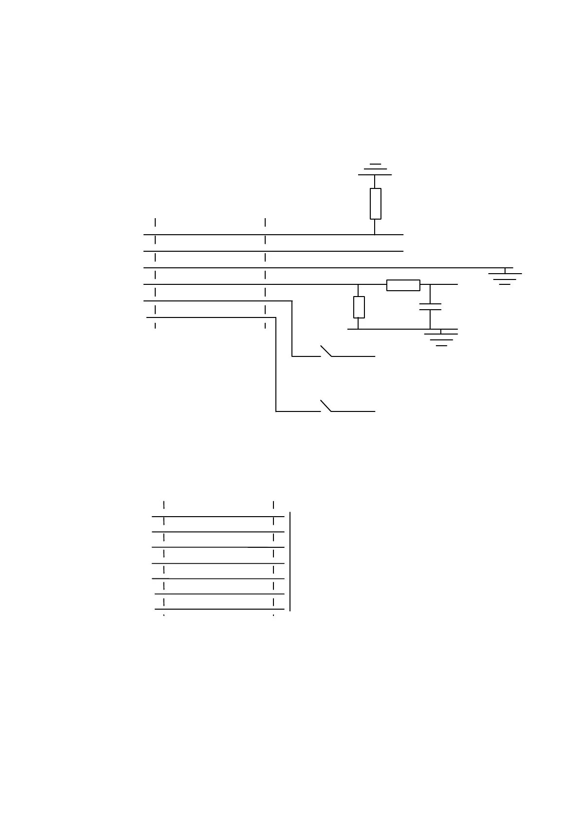
Below are four examples of electrical connections using the available interfaces
provided by the SLS sensor:
Analog output, 0-20 mA
SLS5000
connector
User end
8
11
12
13
14
15
Invalid out -
GND
Invalid out +
Analog out
Laser ON
Power (+24 VDC)
+ 24 VDC
Key switch
+ 24 VDC
Remote control
500 ohm
10 k ohm
10 nF
0-10 V
+ 24 VDC
LOW = Invalid, HIGH = Valid
4.7 k ohm
Figure 18: Analog output with filtering
Selcom synchronous serial interface
SLS
connector
User end
3
5
4
6
11
14
Clock
Data
Clock-inverse
Data-inverse
GND
Laser ON
Connect to SSP connector J1 or J2, ref to SSP manual.
Connect to OIM-II board connector P2, ref to OIM manual.
If an OIM-I board is used the Key switch must be provided,
ref. fig. 4.4.1.
15
Power (+24 VDC)