03-09-05 21
5 INSTALLATION
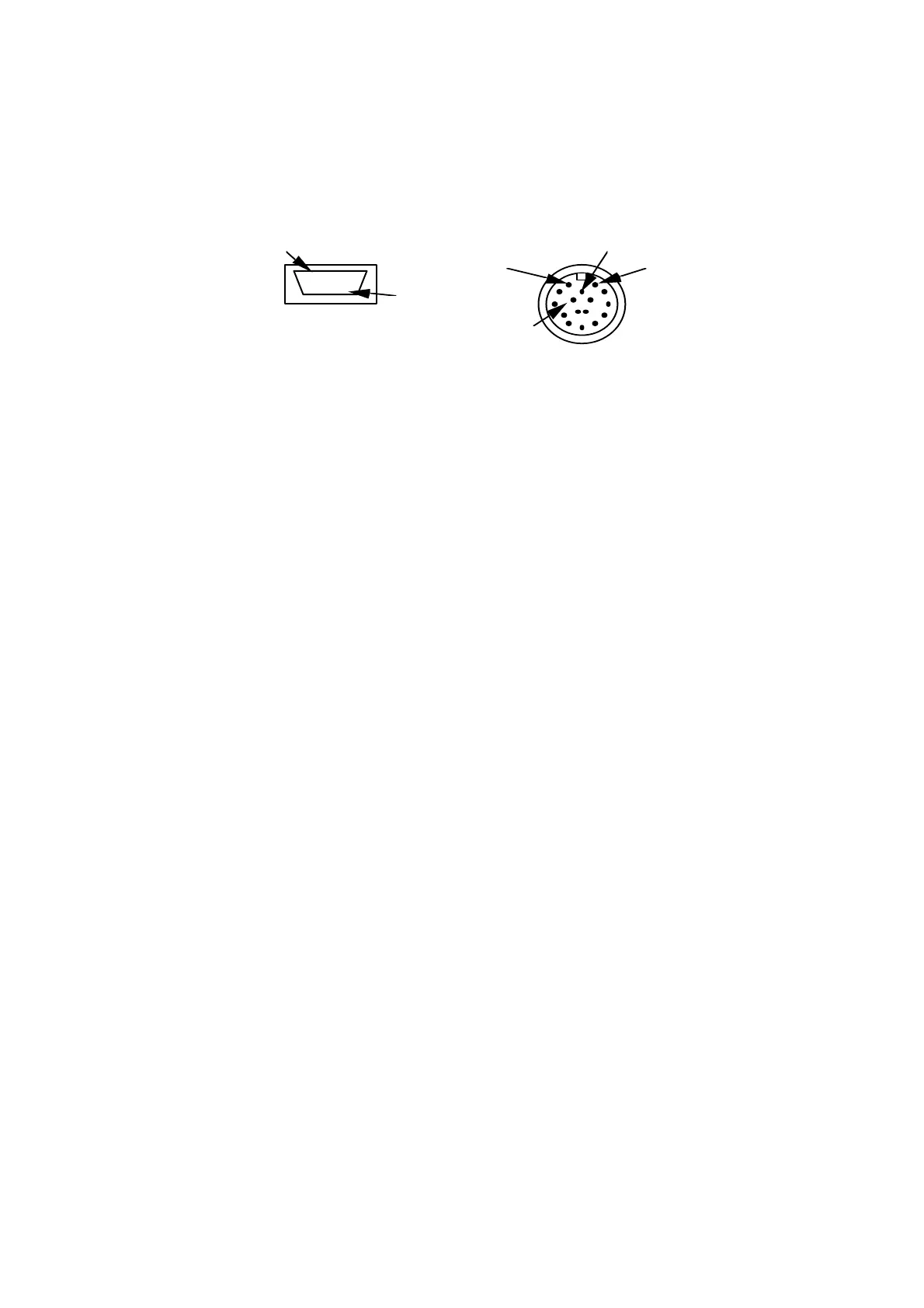
Pin configuration
. . . . .
. . . . .
. . . . .
1
15
DSUB-15 pin, pin connector CONTACT series R2.5-16 pin, pin connector
1 Receive data, RS232-C
9 Transmit data, RS232-C
3 CLOCK, SELCOM interface or RS422 Rx+
4 CLOCK-inv, SELCOM interface or RS422 Rx-
5 DATA, SELCOM interface or RS422 Tx+
6 DATA-inv, SELCOM interface or RS422 Tx-
8 Invalid out-, (when analog interface is used)
12 Invalid out+, (when analog interface is used)
13 Analog out
11 Ground
14 Laser ON, (+24 VDC)
15 Power, (+24 VDC)
1
11
12
16
Figure 12: 15 pin DSUB miniature, pin connector (3 rows) and 16 pin
CONTACT series R2.5, pin connector, front views.
Note: The DSUBmin connector meets IP50 (NEMA 1). The connector may
require extra protection if mounted in a humid environment, although dust alone
will not require any added precautions.
The CONTACT connector meets IP65 (NEMA 4) when connected with mating
connector.
The SLS data can only be accessed through the interface that was specified at the
time of ordering (see serial number label ”Output”).
Cable requirements
Cable length
Interface Pin number Max cable length
RS 232 1, 9, 11 15m
RS 422 or Selcom serial 3, 4, 5, 6
100 m
Analog 11, 13
100 m (<7.5 Ω/signal lead)
Invalid 8, 12 100 m