03-09-05 32
not occur when using special designed sensors for semi transparent materials.
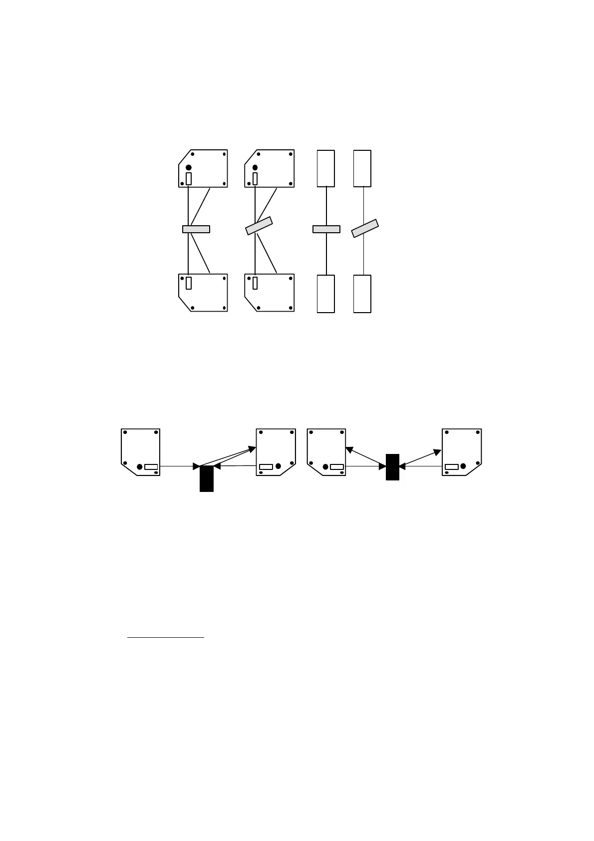
4. Remove the cover over the receiver opening. Put the piece of non-transparent
material in the measurement range. Try to keep it as perpendicular to the laser
beams as possible. If the sensors are correctly aligned you will note an
increase of the thickness when you tilt the plate. A decrease of the thickness
value is an indication that the sensors are misaligned.
Sensor 2
Sensor 1
Sensor 2
Sensor 1
Increase of
thickness
Increase of
thickness
Figure 23: Illustration of item 4 above.
Avoid set-ups where the two sensors can see each other when they are supposed
to measure. A set-up as described in the left figure will produce a variation in the
output value at approximately 1 Hz. See semitransparent materials.
SLS5000
SLS5000
SLS5000
SLS5000
WRONG CORRECT
Figure 24: Dual sensor thickness measurement
Hints for measurements
The SLS sensor is designed to give a true and dependable measurement for a vast
range of materials, surfaces and speed of target/surface.
Sensor features:
1 High speed of light power control.
2 Dynamic range of light power output extremely wide
3 Bandwidth of position data from up to 2 kHz.
4 Sampling rate 16 000 times per second.
5 Small laser spot.
Some materials or surfaces requires some considerations and advises to get the
best possible performance.
The target characteristics can be structured into:
1. Material.